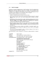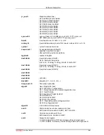
Software Description
ComTec GmbH
5-21
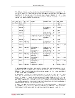
The following table shows the possible data formats for TDC list data characterized by the
time_patch parameter, together with the maximum possible sweep length. Bit 0..3 contain for all
data formats the channel number 1..6, where 6 means the start channel. Bit 3 is the edge
information, 1 means falling edge. In some combinations a "Data lost" bit provides information if
the fast FIFO was full (relevant only for MPA4T).
Time_patch
value (hex)
Data
length
Data lost
bit
Tag bits
Sweep counter
Time
bits
Max. sweep
length
0
2 bytes -
-
-
12
0.4096 µs
5
4 bytes -
-
8 (Bit[24:31] =
Sweeps[0:7])
20
0.105 ms
1
4 bytes -
-
-
28
0.027 s
1a
6 bytes -
-
16 (Bit[32:47] =
Sweeps[0:15])
28
0.027 s
2a
6 bytes -
8 (Bit[40:47] = Tag[0:7]
8 (Bit[32:39] =
Sweeps[0:7])
28
0.027 s
22
6 bytes -
8 (Bit[40:47] = Tag[0:7]
-
36
6.872 s
32
6 bytes 1 (Bit[47])
-
7 (Bit[40:46] =
Sweeps[0:6])
36
6.872 s
2
6 bytes -
-
-
44
1759.2 s = 0.49 h
5b
8 byte
1 (Bit[63])
15 (Bit[48:62] =
Tag[0:14])
16 (Bit[32:47] =
Sweeps[0:15])
28
0.027 s
Db
8 byte
-
16 (Bit[48:63] =
Tag[0:15])
16 (Bit[32:47] =
Sweeps[0:15])
28
0.027 s
f3
8 byte
1 (Bit[47])
16 (Bit[48:63] =
Tag[0:15])
7 (Bit[40:46] =
Sweeps[0:6])
36
6.872 s
43
8 byte
1 (Bit[63])
15 (Bit[48:62] =
Tag[0:14])
-
44
1759.2 s = 0.49 h
c3
8 byte
-
16 (Bit[48:63] =
Tag[0:15])
-
44
1759.2 s = 0.49 h
3
8 byte
1 (Bit[63])
5 (Bit[58:62] = Tag[0:4]) -
54
500.4h = 20.85 d
If ADCs are enabled, only 8 byte data length or multiples of 8 byte for coincidence data are
possible. In the table for TDC list data only the last 6 rows can then occur. Bit 0..2 of an 8 byte
data word signals if it is TDC data, then it is the channel number 1..6, if it is a timer event, then it
is zero, or ADC data, then it is seven.
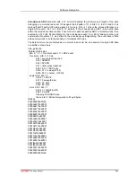
A
timer event
is inserted every millisecond, if ADCs are enabled. Bit 0..3 is 1000 for a timer
event. Bit 4 signals a counter preset reached, bit 5 signals armed TOF logic, bit 6 signals an
active TOF sweep, bit 7 signals real time preset reached. Bits 8..15 signal if ADC1..8 are busy
(corresponding bit is zero) or not. So the number of timer events with corresponding ADC busy
bits of 0 gives the live time of the ADC. By comparing it with the real time, that is the number of
timer events, the dead time is calculated and displayed in the software. Bits 16..31 are the lowest
16 bits of the sweep counter, bits 32..63 is the counter 1.
A 64-bit
single ADC
data word has the bit pattern 111 in the three lowest bits, the ADC number
0..7 in bits 3..5, and a zero in bit 6. Bits 6..15 are the lowest 9 bits of the sweep counter. Bits
16..31 is the 16 bit ADC data. Bits 32..63 is the time of the ADC single event in units of 6.4 ns.

