

Hardware Description
ComTec GmbH
3-8
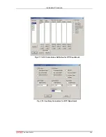
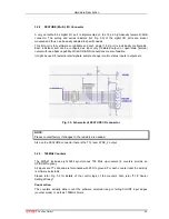
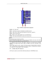
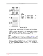
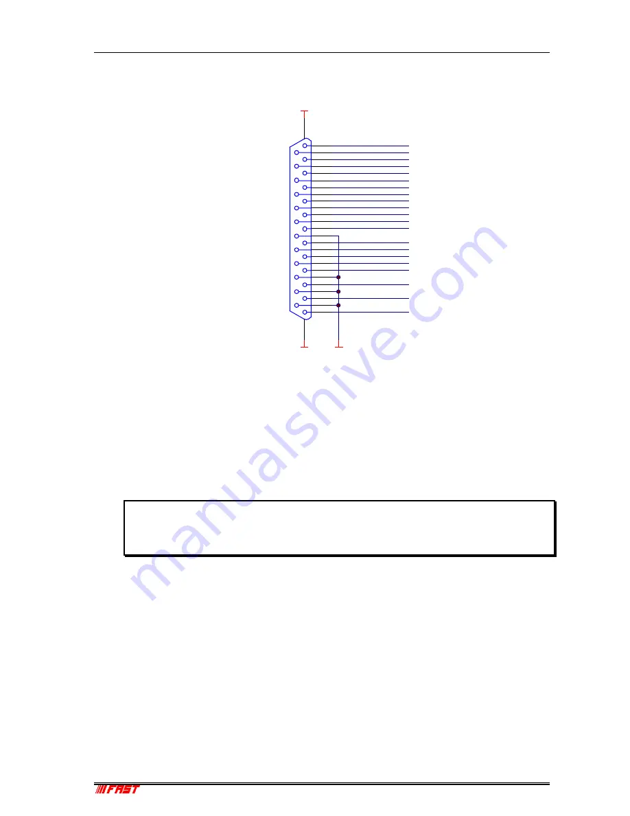
DATA 0…15
– Data inputs
DRDY
– Data Ready input signal indicating that valid data is present
DACC
– Data Accepted output signal indicating that the input data is registered
DEAD
– Dead Time input signal
ENC
– Enable Converter output signal to arm the connected device
DENB
– Data Output Enable signal to enable tri-state output drivers
NOTE:
When using cables with all pins connected:
unused input signals should be tied to a valid level with low impedance since open wires tend to
act as an antenna and might disturb proper data acquisition.
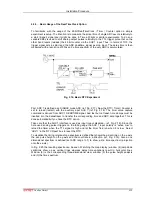
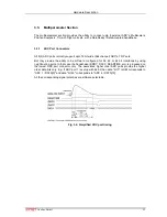
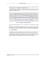
The handshake in fact is quite easy. When DRDY is asserted by the external device the MPA4
registers the valid data and then asserts DACC unitl DRDY is removed. Then DACC is also
removed.
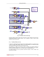
Always 4 ADC ports in a row (1…4 and 5…8) share a queue for the data transfer to the FIFO.
Thus, the response time of each interface may vary by the number of simultaneously firing ADC's
(ref. chapter 8.3.2 "ADC port DRDY / DACC handshake").
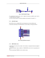
3.3.2. Auxiliary / Reject I/O Connectors
3 BNC type connectors provide additional flexibility particularly in COINCIDENCE mode.
1
14
2
15
3
16
4
17
5
18
6
19
7
20
8
21
9
22
10
23
11
24
12
25
13
M1
M2
DB25F-B
GND
GND
DATA 0
DATA 1
DATA 2
DATA 3
DATA 4
DATA 5
DATA 6
DATA 7
DATA 8
DATA 9
DATA 10
DATA 11
DATA 12
GND
DRDY
DACC
ENC
DEAD
DENB
DATA 13
DATA 14
DATA 15
Fig. 3.7: ADC Port connectors' pin assignment