
Software Description
ComTec GmbH
5-15
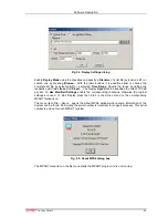
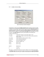
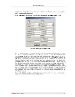
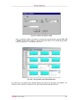
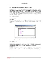
You have a choice between several formulas to combine two parameters:
Sum
= left + right
makes a sum spectrum, and
Diff
= Range + left - right can be used to subtract two spectra. The
Range
and
Name
can be defined in the edit fields or default values will be taken. Any such
calculated spectrum can be used as a parameter for a new dual parameter spectrum. If
Conditions are defined, one can be selected as a necessary
Condition
for incrementing a
channel in this spectra. The
COPY
type of spectra allows to set conditions for copies of primary
spectra. Of course this "copy" can be quite different from the primary spectra, as only the first
stop event after the time threshold is selected. For ADC inputs in addition the
Pos
= Range * right
/ (left + right) formula is available, that is often used for position dependent detectors read out
from both sides, and the Division formula
Div
= Range * left / right can be used to divide two
spectra. The
Range
and
Name
can be defined in the edit fields or default values will be taken.
Any such calculated spectrum can be used as a parameter for a multi parameter spectrum. If
Conditions are defined, one can be selected as a necessary
Condition
for incrementing a
channel in this spectra. The
COPY
type of spectra allows to set conditions for copies of primary
ADC spectra.
HISTORY
allows to display a history plot of an ADC as a new spectra, i.e. you can
see the data of the ADC as they come in versus the event number. The length of the history plot
can be defined free, just edit the Range number.
Spectra containing the sum of counts from several ADC's can be used to create a "superdetector"
from multiple smaller detectors. It doesn't matter if the ADC's are used in single or coincidence
mode, the sum spectra is calculated from the complete single spectra. Select the "
Or = Sum of
counts
" radio button.
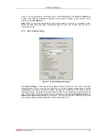
Fig. 5.19: Calculated Spectrum Setting