background image

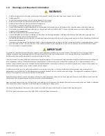
WARNING

Be sure to read, understand, and follow all instructions and warnings in this manual. 

Any misuse could result in serious injury or death. 

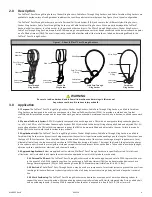
3.0  Application


3.1 Purpose: The FallTech® Pass-Through Sling Anchors, Choker Sling Anchors, Cable Pass-Through Sling Anchors, and Cable Carabiner  


Sling Anchors are designed to be used as a component in a Personal Fall Arrest System (PFAS), to provide a combination of worker 


mobility and fall protection as required for inspection work, general construction, maintenance work, oil production, confined space work,  

 etc. 
 

3.2 Personal Fall Arrest System: A PFAS is typically composed of an anchorage and a FBH, with an energy absorbing connecting device,    


i.e., a EAL, an SRD, or a Fall Arrester Connecting Subsystem (FACSS), attached to the dorsal D-ring of properly fitted and adjusted FBH. All    


uses and applications of a FBH with this equipment requires the FBH to be properly fitted and adjusted to the user. Failure to properly 


fit the FBH to the user could result in serious injury or death.  


3.3 Application Limits: The FallTech® Pass-Through Sling Anchors, Choker Sling Anchors, Cable Pass-Through Sling Anchors, and Cable 


Carabiner Sling Anchors are a dynamic anchorage subsystem that varies in its performance depending upon the length of the system, and   


the type of PFAS system used.  Care should be taken to understand the capacity of the system, anchorage strength requirements, total 


allowable free fall, and the requirements how the user’s PFAS deploys during a fall event.  The longer the freefall, the greater the energy    


in the system and will result in more significant clearance requirements and impact forces on the body.  Take action to avoid sharp edges,   


abrasive surfaces, and thermal, electrical, and chemical hazards.


3.4 Approved Applications: Below are applications for which all FallTech® Pass-Through Anchors are specifically suited. This list is not  


all-inclusive, but is intended to anticipate the most common applications in which this product may be used.

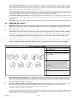
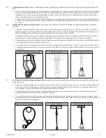
  3.4.1 Personal Fall Arrest: The FallTech® Pass-Through Anchors used as the anchorage component of a PFAS to protect the user   


in the event of a fall. PFAS typically consists of an anchorage, a Full Body Harness (FBH), and a deceleration device such as a 


Energy Absorbing Lanyard (EAL) or Self Retracting Device (SRD). Maximum permissible free fall is 6 ft (1.8 m).

  3.4.2 Restraint: The FallTech® Pass-Through Anchors may be used as a component of a restraint system to prevent the user from  


reaching a fall hazard. Restraint systems typically include a full body harness containing a body belt and a lanyard or restraint    

  line. 
  3.4.3 Work Positioning: The FallTech® Pass-Through Anchors may be used as a component of a work positioning system to  


support the user at a work position. Work positioning systems typically include an FBH with integrated side D-rings, a body belt,   


and a positioning lanyard. A back up PFAS is required when the user is exposed to a free fall of 2 ft (1.8 m) or more.

MANC03 Rev B

040320

4

2.0  Description


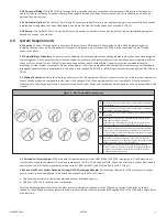
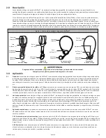
The FallTech® Pass-Through Sling Anchors, Choker Sling Anchors, Cable Pass-Through Sling Anchors, and Cable Carabiner Sling Anchors are  


available in a wide variety of configurations to address the specific needs in most workplaces. See Figure 1 for a typical configuration.


The FallTech® Pass-Through Anchors are part of a Personal Fall Arrest System (PFAS) and come in four different styles; Sling Anchors,  


Choker Sling Anchors, Cable Pass-Through Sling Anchors, and Cable Carabiner Sling Anchors. When properly employed the FallTech® 


Anchors will allow the user to safely anchor to I-Beams and other constructs. The PPass-Through Sling Anchors, Choker Sling Anchors,  


Cable Pass-Through Sling Anchors are part of a PFAS requiring a compatible connector or device connected to the dorsal connection point   


on a Full Body Harness (FBH). The user is required to read and be familiar with all the instructions, labels, and warnings affixed to the 


FallTech® Pass-Through Anchor.  

Figure 1 - About FallTech® Pass-Through Anchors

Pass-Through

Sling Anchor

Choke-On

Sling Anchor

Cable Pass-Through

Sling Anchor

Carabiner

Sling Anchor

Subsystem 

Connector

Pass-Through

D-Ring

Wear Pad

Structural

Member

Subsystem 

Connector

Web Loop

Wire Rope

Pass-Through

O-Ring

Subsystem 

Connector

Wire Rope

Connector 

D-Ring

Subsystem 

Connector

Carabiner

Summary of Contents for 7324

Page 1: ...9 4619 Fax 323 752 5613 This manual is intended to meet the Manufacturer s Instructions as required by the American National Standards Institute ANSI Z359 and Canadian Standards Association CSA Z259 a...

Page 2: ...2 MANC03 Rev B 040320 2 For purposes of this manual the FallTech Pass Through Sling Anchors Choker Sling Anchors Cable Pass Through Sling Anchors and Cable Carabiner Sling Anchors in all iterations ma...

Page 3: ...fall arrest forces placed on the user s body In addition the onset of suspension trauma after a fall even may be accelerated for heavy users The user of the equipment discussed in this manual must rea...

Page 4: ...d as the anchorage component of a PFAS to protect the user in the event of a fall PFAS typically consists of an anchorage a Full Body Harness FBH and a deceleration device such as a Energy Absorbing L...

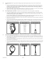
Page 5: ...s snap hook or carabiner and webbing cable or rope F Never attach in a manner where an element of the connector gate or release lever may become caught on the anchor thereby producing additional risk...

Page 6: ...ussed in this manual include the height of the anchor point relative to the user s FBH D ring i e overhead see Lanyard example in Figure 3 1 1 2 2 3 3 A B C D E F A 6 ft 1 8 m Length of Shock Absorbin...

Page 7: ...han one time The yellow wear pad must be installed on the anchorage side as shown on Figure 5 Figure 5 Pass Through Anchor Installation Figure 6 Installation 2 Ensure ensure that the Pass Through Slin...

Page 8: ...allation Figure 12 Installation Figure 13 Load Direction 15o 15o 5 9 Cable Carabiner Anchor Installation Ensure that the rated structural member is free of sharp jagged or abrasive edges 1 Place the C...

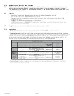
Page 9: ...ected by a competent person other than the user at least once each year or more frequently if the conditions exist FallTech strongly recommends that a competent person conducts a hazard assessment of...

Page 10: ...erial _________________________ Date of Manufacture _________________________ INSPECTION DATE INSPECTOR COMMENTS PASS FAIL CORRECTIVE ACTION NEEDED APPROVED BY 7 4 Inspection Document Record inspectio...

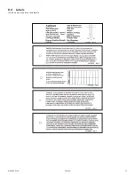
Page 11: ...8 0 Labels The labels must be present and legible MANC03 Rev B 040320 11...

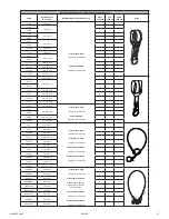
Page 12: ...r Webbing 5 000 lbs 22 2 kN Min P 7245 36 in 0 9 m P 72493FT P 72494FT 48 in 1 2 m P 72496FT 72 in 1 8 m P 7427 4 ft 1 2 m Alloy Steel D Ring 5 000 lbs 22 2 kN Min Alloy Steel O Ring 5 000 lbs 22 2 kN...

Page 13: ...323 752 5613 El objetivo de este manual es cumplir con las instrucciones del fabricante seg n lo exige el American National Standards Institute ANSI Z359 y la Canadian Standards Association CSA Z259...

Page 14: ...los fines de este manual los anclajes de eslinga con paso de FallTech los anclajes de eslinga tipo gargantilla los anclajes de eslinga con paso de cable y los anclajes de eslinga de mosquet n con cabl...

Page 15: ...a aparici n de traumatismos por suspensi n despu s de una ca da puede incluso acelerarse para usuarios pesados El usuario del equipo que se describe en este manual debe leer y comprender el manual com...

Page 16: ...pero tiene la intenci n de anticipar las aplicaciones m s comunes en las que se puede usar este producto 3 4 1 Protecci n personal contra ca das los anclajes con paso de FallTech utilizados como compo...

Page 17: ...uridad en los dos anillos en D laterales o de posici n de manera que los anillos en D encajen en las compuertas las puertas de un esparcidor siempre deben estar alejadas de los anillos en D durante el...

Page 18: ...anual incluyen la altura del punto de anclaje en relaci n con el anillo en D del FBH del usuario es decir arriba vea el ejemplo de Cuerda en la Figura 3 1 1 2 2 3 3 A B C D E F A 6 pies 1 8 m Longitud...

Page 19: ...de desgaste amarilla debe instalarse en el lado del anclaje como se muestra en la Figura 5 Figura 5 Instalaci n de anclaje con paso Figura 6 Instalaci n 2 Aseg rese de que el anclaje de eslinga con pa...

Page 20: ...del ancla tipo gargantilla Figura 12 Instalaci n Figura 13 Direcci n de carga 15O 15O 5 9 Instalaci n del anclaje del mosquet n de cable aseg rese de que el miembro estructural nominal no tenga bordes...

Page 21: ...ente que no sea el usuario al menos una vez al a o o con mayor frecuencia si existen las condiciones FallTech recomienda encarecid amente que una persona competente realice una evaluaci n de peligros...

Page 22: ...__ Fecha de fabricaci n _______________________ Fecha de inspecci n Inspector Comentarios Pas no pas Se hace necesaria una acci n cor rectiva Aprobado por 7 4 Documentaci n de la inspecci n registre l...

Page 23: ...8 0 Etiquetas Las etiquetas deben estar presentes y ser legibles MANC03 Rev B 040320 23...

Page 24: ...45 36 pulg 0 9 m P 72493FT P 72494FT 48 pulg 1 2 m P 72496FT 72 pulg 1 8 m P 7427 4 pies 1 2 m Anillo en D de aleaci n de acero 5 000 libras 22 2 kN M n Junta t rica de aleaci n de acero 5 000 libras...

Page 25: ...2 5613 Ce manuel est con u en conformit avec les consignes du manufacturier tel que requis par l American National Standards Institute ANSI Z359 et l Association canadienne de normalisation CSA et doi...

Page 26: ...20 26 Aux fins du pr sent manuel les ancres de passage pour lingues FallTech les ancrages pour lingues tranglement les ancrages pour lingues passage de c ble et les ancrages pour lingues mousqueton de...

Page 27: ...lus l apparition d un choc par suspension apr s une chute est plus courante chez les personnes physiquement lourdes L utilisateur de l quipement dont il est question dans ce manuel doit lire et compre...

Page 28: ...cialement adapt es se trouvent ci dessous Cette liste n est pas exhaustive mais vise anticiper les applications les plus courantes dans lesquelles ce produit peut tre utilis 3 4 1 Syst me antichute p...

Page 29: ...squeton d carteur deux anneaux en D lat raux de mani re ce que les anneaux en D s engagent dans les ports les ports d un carteur doivent toujours faire face aux anneaux en D pendant le positionnement...

Page 30: ...on dans ce manuel afin de s assurer qu il existe un d gage ment ad quat dans la trajectoire de chute Les variables discut es dans ce manuel incluent la hauteur du point d ancrage par rapport l anneau...

Page 31: ...au D et en le faisant passer plus d une fois par celui ci Le tampon d usure jaune doit tre install du c t de l ancrage comme indiqu sur la figure 5 Figure 5 Installation de l ancre de passage Figure 6...

Page 32: ...d tranglement Figure 12 Installation Figure 13 Direction de la charge 15o 15o 5 9 Installation de l ancrage mousqueton de c ble S assurer que l l ment de structure valu est exempt de bords coupants d...

Page 33: ...e personne comp tente autre que l utilisateur au moins une fois par an ou plus fr quemment si les conditions le permettent FallTech recommande fortement qu une personne comp tente proc de une valuatio...

Page 34: ..._____________ Date de fabrication _________________________ DATE D IN SPECTION INSPECTEUR COMMENTAIRES SUCC S CHEC MESURES CORRECTIVES N CES SAIRES APPROUV PAR 7 4 Document d inspection Inscrire les r...

Page 35: ...8 0 tiquettes Les tiquettes doivent tre pr sentes et lisibles MANC03 R v B 040320 35...

Page 36: ...2 2 kN Min P 7245 36 po 0 9 m P 72493Pi P 72494Pi 48 po 1 2 m P 72496Pi 72 po 1 8 m P 7427 4 pi 1 2 m Anneau en D en acier alli 5 000 lb 22 2 kN Min Anneau en O en acier alli 5 000 lb 22 2 kN Min C bl...

Reviews: