Power supplies
2.
94
Ref.1912
DDS
HARDWARE
· 42 ·
Lights indicating the status of the main power supply
The non-regenerative power supply PS-25B4 has the following lights on the
front panel to indicate the status of the main power supply.
FAULT
BLINKING. The blinking red led indicates that
there are no
errors
and that
one or several mains phases are missing
.
FAULT
turned ON.
The steady red led on indicates that there is an
error. The error is indicated on the display of the drives.
FAULT
turned OFF.
The led off indicates that there is no error and that
all mains phases are OK.
BALLAST
turned ON.
The amber led is lit when the energy dissipating
Ballast circuit is activated.
DC BUS ON.
The green led indicates that the module is supplying all its
power at the DC BUS.
Lights indicating the status of the auxiliary power supply
The non-regenerative power supply PS-25B4 has the following status
indicating lights on the front panel of the module for the integrated internal
auxiliary power supply.
RESET.
Initializes the auxiliary 24 V DC power supply.
OVER VOLTAGE.
The red led indicates that there is an over-voltage error
at the 24 V DC output or due to over-temperature.
OVER CURRENT.
The red led indicates that there is an over-current error
at the 24 V DC output.
ON.
The green led it indicates that there are 24 V DC at the output.
Ballast resistor selection
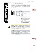
The non-regenerative power supply PS-25B4 had two switches on the front
and next to connector X1 (see figure) for selecting the external Ballast
resistor. If you still have a model like this one, refer to the attached table to
select the right resistor model according to the setting of the switches that
enables the ·I
2
t· protection.
Remember that selecting «protection disabled», internal resistor or RM-15
module means disabling the ·I
2
t· protection. The latter incorporate their own
thermostat for your protection.
For the switch combination shown in the figure and verified in the table, the
selected ballast resistor would correspond to the ER-18/1800 or ER+TH-
18/1000+FAN.
NOTE.
The model with two selection switches has been discontinued. If
you still have this model, refer to this section to configure the selection of
the Ballast resistor. If you have the model with three switches, see the
next page.
T. H2/6
Layout of the Ballast resistor selector switches.
S2
S1 RESISTOR
ON
ON
ER-18/1100
ON
OFF
ER-18/1800 or ER+TH-18/1000+FAN
OFF
ON
ER+TH-18/2200
OFF OFF
Protection disabled
Internal resistor or RM-15 module
represents, in the figure, the moving element of the switch.
Example
S2
S1 RESISTOR
ON
OFF
ER-18/1800 or ER+TH-18/1000+FAN
Disc
ontinue
d model
PS-25B4
ON
S1
S2
Summary of Contents for DDS Series
Page 1: ...DRIVE DDS Hardware manual Ref 1912...
Page 6: ...6 Ref 1912 DDS HARDWARE 6 I This page intentionally left blank...
Page 9: ......
Page 10: ......
Page 11: ......
Page 12: ......
Page 16: ...Ref 1912 DDS HARDWARE 16...
Page 20: ...Ref 1912 DDS HARDWARE 20...
Page 179: ...3 Drives Ref 1912 179 DDS HARDWARE...
Page 180: ...3 Drives Ref 1912 DDS HARDWARE 180...
Page 200: ...4 AUXILIARY MODULES Auxiliary modules Ref 1912 DDS HARDWARE 200...
Page 260: ...7 Cables Ref 1912 DDS HARDWARE 260...
Page 397: ...Sales models 12 Ref 1912 397 DDS HARDWARE 12 9 Order example F H12 21 Order example...
Page 404: ...13 Compatibility Ref 1912 DDS HARDWARE 404...
Page 405: ......


