background image


4

TLP Pro 725C Series • Setup Guide (Continued)

Step 3 — Run all Cables

Run all cables necessary to support the AC connector, the cables stored in the cubby, and all planned AAP connectors. Run the 
cables below the table and through the hole that was cut in 

Step 2 — Cut the Surface

 on the previous page. Leave enough slack 

in the cables to connect or route them before the cubby is installed in the table. Leave enough space under the TLP Pro 725C 
enclosure for the external power supply and connection of AV cables and the network connection.

Step 4 — Install Cable Retractors (Optional)

If required, Extron cable retractors must be purchased separately. It is difficult to mount the Cable Cubby into the table after the 
retractors have already been installed so Extron recommends installing the empty retractor bracket at this point. The bracket 
should be secured using the lowest level of mounting holes inside the touchpanel enclosure.
The retractors should be added to the bracket after 

Step 8 — Mounting the Enclosure

 on page 6. For complete information 

about retractors and how to install them, see the 

TLP Pro 725C User Guide

 and 

Retractors User Guide

 at 

www.extron.com

.

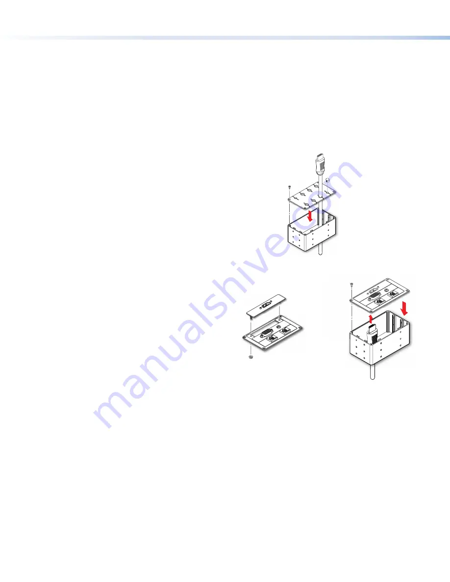
Step 5 — Assemble Pass-through Cable Module (Optional)

1. 

Pass the cables through the connectivity module from the bottom (see 
figure 5, 

1

).

2. 

Insert the cable into the grommet plate (

2

).

3. 

Fill any unused holes with the provided plugs (

3

).

4. 

Attach the grommet plate to the top of the connectivity module, using 
four of the provided #4-40 thread forming screws (

4

).

To secure the pass-through cable module to the Touchpanel enclosure, see 

Step 7 — Install Modules

 on the next page.

3

2

1

4

Figure 5. 

Installing pass-through cable module

Step 6 — Assemble AAP Module (Optional)

If required, AAPs must be purchased separately. Go to 

www.extron.com

 to see the full range of AAPs that are 

available.

1. 

Secure up to three single space AAPs in the AAP Frame, 
using the #4-40 nut with captive washer provided with the 
AAP (figure 6, 

1

).

If required, fill any unused spaces with blank AAP plates.

2. 

Insert cables through the bottom of the connectivity 
module and connect them to the AAPs (

2

).

3. 

Secure the AAP frame to the connectivity module, using 
four of the provided #4-40 thread forming screws (

3

).

To secure the AAP module to the Touchpanel enclosure, see 

Step 7 — Install Modules

 on the next page.

3

2

#4-40 Nut with 
Captive Washer

1

AAP

AAP Frame

Connectivity
Module

3

3

3

3

Figure 6. 

Assemble the AAP Module

Summary of Contents for TouchLink TLP Pro 725C Series

Page 1: ...el Toolbelt Provides device discovery device information firmware updates and configuration of network settings system utilities and user management for TouchLink Pro devices Global Scripter Provides an integrated development environment for Extron control systems programming NOTE All four software programs are available from www extron com Obtain the following network information from your networ...

Page 2: ...tor to the LAN and power it on see figure 9 Set up the Touchpanels for Network Communication Connect the PC that you are using for setup the control processor and the touchpanel to the same Ethernet subnetwork Use the Setup Menu see page 8 or Toolbelt to set the DHCP status and if necessary the IP address subnet mask gateway and related settings for the touchpanel Configure the Touchpanels The GUI...

Page 3: ...C Series User Guide There are three methods for cutting the hole in the table Using a hand router Recommended method Use the Extron TLP Pro 725C routing template see Installation Routing Templates for Cable Cubby Series 2 Enclosures at www extron com Refer to the Routing Template User Guide available at www extron com to prepare the template and use the template to cut the hole NOTE The metal rout...

Page 4: ...Guide and Retractors User Guide at www extron com Step 5 Assemble Pass through Cable Module Optional 1 Pass the cables through the connectivity module from the bottom see figure 5 1 2 Insert the cable into the grommet plate 2 3 Fill any unused holes with the provided plugs 3 4 Attach the grommet plate to the top of the connectivity module using four of the provided 4 40 thread forming screws 4 To ...

Page 5: ...on secteur autre que le modèle Cable Cubby AC Power Module To install the power cable pass through or AAP modules follow these instructions 1 Insert the module into the cable cubby figure 7 1 Make sure the mounting holes on the module line up with the holes on the Cable Cubby enclosure If you are installing retractors they should be secured using the lowest level of mounting holes inside the touch...

Page 6: ...d and ensure that the lever is down Slide the clamp all the way up against the bottom of the table Ensure the TLP Pro 725C is firmly seated in the table Rotate the lever up to secure the enclosure 2 1 3 Lever Figure 8 Mounting the TLP Pro 725C Enclosure Locking Plate NOTE To lower the side clamp turn the lever down then press and hold the locking plate while sliding down the clamp 2 Rotate the sid...

Page 7: ...l and at least 15 from the center axis When no motion has been detected for a user defined period of time the touchpanel enters sleep mode When motion is detected by the sensor the screen display is restored and active C Communication LED This LED shows the configuration and connection status of the touchpanel Unlit during normal operation the touchpanel is configured and connected to an IP Link P...

Page 8: ... to the unit Use this mode with Toolbelt software to replace firmware in the event of conflicts arising from uploading a firmware update Reset All IP Settings Press and hold the Reset button for 6 seconds After the Reset LED C flashes twice release and momentarily press the Reset button Use this mode to reset all network settings without affecting user loaded files Reset to Factory Defaults Press ...

Reviews: