Operation
•
Rear Discharge Units:
Torque the 3/8 nyloc nut to 30-35 ft-lb (41-47
N-m) (see Figure 19 ).
Figure 19
1.
3/8 inch nyloc-torque to
50-55 ft-lb (68-75 N-m)
3.
Wheel spacer
2.
Anti-scalp rollers
4.
3/8-16 X 7 3/8 inch bolt
Note:
The foot operated deck lift assist lever can be
used to momentarily lift the deck to clear objects. Be
sure that PTO is disengaged.
Adjusting the Side Bumpers
(Rear Discharge Units Only)
Mount the side bumpers in the top holes when
operating in height of cuts higher than 2 1/2 inches
(64 mm) and in the center holes when operating in
height of cuts lower than 2 1/2 inches (64 mm).
Note:
When bumpers become worn, switch the
bumpers to the opposite sides of the mower, flipping
them over. This allows the bumpers to be used longer
before replacing them.
1. Stop the machine and move the motion control
levers outward to the neutral locked position.
2. Disengage the PTO.
3. Engage the park brake.
4. Stop the engine, remove the key and wait for all
moving parts to stop.
5. Position the transport lock in the latching
position.
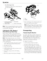
6. Remove the bolts and nuts from each bumper.
Figure 20
1.
Bolt
3.
Nut
2.
Bumper
7. Move each bumper to the desired position and
secure them with the bolts and nuts.
Note:
Only use the top or center sets of holes to
adjust the bumpers. The bottom holes are used
when switching sides, at which time they become
the top holes on the other side of the mower.
Transporting
Transporting the Machine
Use a heavy-duty trailer or truck to transport the
machine. Ensure that the trailer or truck has all
necessary lighting and marking as required by law.
Thoroughly read all of the safety instructions.
Knowing this information could help you, your
family, pets, or bystanders avoid injury.
To transport the machine:
•
Lock the brake and block the wheels.
•
Be sure the fuel shut-off valve is closed.
•
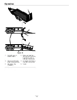
Securely fasten the machine to the trailer or
truck with straps, chains, cable, or ropes. Only
use the four designated tie-down locations on
the mower–two on the left side and two on the
right (see Figure 21). Use these locations even
when transporting the mower with an attached
accessory. Using non-designated locations may
cause damage to the mower and/or attachment.
32
Summary of Contents for RADIUS
Page 1: ...RADIUS For Serial Nos 400 000 000 Higher Part No 4502 907 Rev B ...
Page 73: ...Schematics Schematics Electrical Logic Schematic Exmark Engine 73 ...
Page 74: ...Schematics Electrical Logic Schematic Kohler Engine 74 ...
Page 75: ...Schematics Electrical Logic Schematic Kawasaki Engine 75 ...
Page 79: ...Notes 79 ...
Page 80: ...Notes 80 ...
Page 81: ...Service Record Date Description of Work Done Service Done By 81 ...
Page 82: ...82 ...


