


Description of Event Types
292
FTB-700 Series
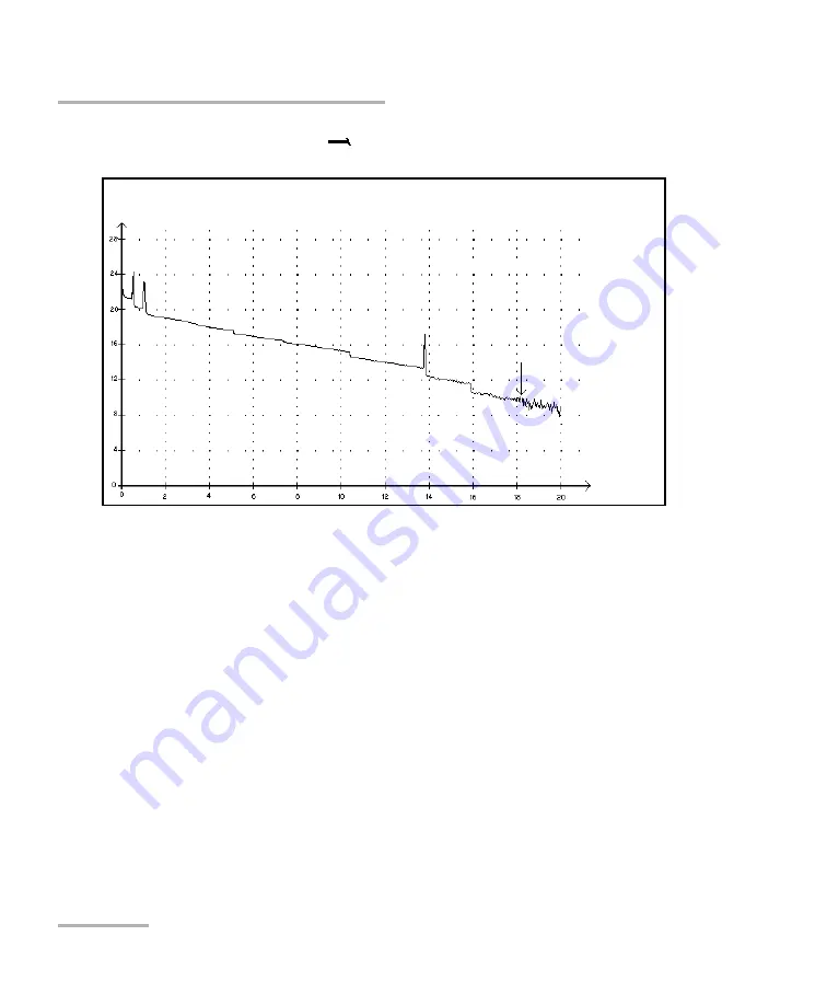
End of Analysis
End of Analysis
This event indicates that the pulse width used did not provide enough
dynamic range to get to the end of the fiber.
³
The analysis ended before reaching the end of the fiber because the
signal-to-noise ratio was too low.
³
The pulse width should therefore be increased so the signal reaches
the end of the fiber with a sufficient signal-to-noise ratio.
³
There is no loss or reflectance specified for end-of-analysis events.
Reflected power
(dB)
Distance
(km)


