Evolution Fury 6 Original Instructions Manual Download Page 20

www.evolutionfury.com

20

NOTE: 

Always make a ‘dry run’ with the 

machine switched ‘off’ so that the path of 
the blade can be checked. Some Bevel and 
Compound Cuts may require the Hold Down 
Clamp to be positioned to the RH side of the 
Cutting Head. This may be necessary to avoid 
interference with the blade and other parts of 
the machine as the Cutting Head is lowered.  
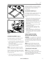
8. Fence Adjustment

NOTE: 

The left hand side of the fence is 

provided with additional adjustments. The 
upper portion of the fence can slide to the 
left to provide clearance for the blade. This 
may be necessary when acute bevel angles 
are selected.

To adjust the fence:

•  Loosen the thumbscrew. 

(Fig 14)

•  Slide the upper portion of the fence to 

the required position and tighten the 
thumbscrew.

•  Lower the Cutting Head to check the path 

of the blade. Ensure there is no interference 
with any other parts of the machine.

9. Compound Cutting

A Compound Cut is a combination of a Mitre 
Cut and  Bevel Cut.
•  Set the Mitre Angle required as previously 

described.

•  Set the Bevel Angle as previously described.
•  Ensure the tightness of all adjustment/

locking screws, and conduct a ‘dry run’ to 
check the path of the blade.

•  Make the cut as previously described.

10. Cutting Bowed Material  (Fig 15)

Before cutting any workpiece, check to see 
if it is bowed. If it is bowed the workpiece 
must be positioned and cut as shown. Do not 
position the workpiece incorrectly or cut the 
workpiece without the support of the fence.

11. Clearing Jammed Material

•  Turn mitre saw “OFF” .and allow the 

blade to come to a complete halt.

•  If possible allow the Cutting Head to rise 

to its upper position.

•  Unplug the Mitre Saw from the mains 

supply.

•  Carefully remove any jammed material 

from the machine.

Fig. 15

Fig. 14

Summary of Contents for Fury 6

Page 1: ...210mm TCT Multipurpose Mitre Table Saw Original Instructions Read instructions before operating this tool www evolutionfury com 16 04 12_V9...

Page 2: ...www evolutionfury com 2 03 GB...

Page 3: ...imited Warranty 5 General Safety Rules 5 Additional Specific Safety Rules 7 Safety Labels and Symbols 8 Machine Overview 12 13 Operation Mitre Saw 16 Operation Table Saw 21 Maintenance 24 Environmenta...

Page 4: ...hine Directive 2006 95 EC Low Voltage Directive 2004 108 EC EMC Directive 2002 95 EC Restriction of the use of Certain Hazardous Substances in Electrical and Electric Equipment Standards and Technical...

Page 5: ...air or replace it with the same or equivalent item There is no warranty written or verbal for saw blades In no event shall Evolution Power Tools be liable for loss or damage resulting directly or indi...

Page 6: ...t on 17 Avoid unintentional starting Ensure switch is in off position when plugging in 18 Use outdoor extension leads When the tool is used outdoors use only extension cords intended for outdoor use a...

Page 7: ...ion cord be sure to use one that is heavy enough to carry the current that your tool will draw An undersized cord will cause a drop in line voltage resulting in loss of power and overheating 9 Do not...

Page 8: ...safety glasses with side shield and a full face shield when needed WARNING If any parts are missing do not operate your table mitre saw until the missing parts are replaced Failure to follow this rule...

Page 9: ...dition and wear A damaged or worn blade should be replaced immediately Beware of ejecting chips as they may be HOT Always make provision for the safe handling of excess material Keep machine base and...

Page 10: ...epth mm 32 mm Noise and Vibration Data Sound pressure level 106 3dB A K 3dB A Sound power level 119 3dB A K 3dB A Vibration level 2 5 m S2 K 1 5dB A The declared vibration total value has been measure...

Page 11: ...Riving Knife Adjustment 1 Multi Purpose Blade Fitted 1 Rip Fence Bevel Guide Assembly 1 Auxiliary Lower Blade Guard Fitted 1 Dust Bag Adaptor Tube 1 Workpiece Supports 2 Rear Stabilising Arms 2 Addit...

Page 12: ...Y TABLE 3 RETRACTABLE LOWER BLADE GUARD 4 BLADE 5 BEVEL LOCKING LEVER Back of the machine 6 MITRE ANGLE LOCKING SCREW 7 MITRE ANGLE SCALE 8 FENCE 9 HOLD DOWN CLAMP 10 STABILISING ARMS X2 Back of machi...

Page 13: ...TCH Inside handle 2 ON OFF LATCHING SWITCHES 3 CUTTING HANDLE 4 TABLE TOP 5 AUXILLIARY LOWER BLADE GUARD 6 UPPER BLADE GUARD 7 RIP FENCE 8 PUSH STICK 9 MOUNTING HOLE 2 at the front and 2 under the sta...

Page 14: ...nd stored safely for possible future use 1 Tighten the mitre and bevel locks 2 Position the saw so other people cannot stand behind it Thrown debris could injure people in its path 3 Place the saw on...

Page 15: ...he extraction port at the rear of the machine Fig 3a 3b Push the adaptor tube into the extraction port at the rear of the machine Slide the Dust Bag onto the adaptor tube ensuring that the spring clip...

Page 16: ...and acted upon Failure to carry out the configuration procedure could result in damage to the machine and or injury to the operator Loosen the table height adjustment screw Fig 4 Raise the table top t...

Page 17: ...into the socket that best suits the cutting application ensuring that it is pushed fully down Tighten the fence thumbscrew to lock the pillar of the Hold Down Clamp into the fence socket Put the workp...

Page 18: ...m the blade Pictograms on the machines rotary table are provided as an aid to safe working practices Keep hands away from the path of the blade Hold the workpiece firmly to the fence to prevent any mo...

Page 19: ...re provided for every 50 of angular movement Note The rotary table must always be locked into position with the Mitre Angle Locking Screw even if a positive stop is selected To select a Mitre Angle Lo...

Page 20: ...utting Head to check the path of the blade Ensure there is no interference with any other parts of the machine 9 Compound Cutting A Compound Cut is a combination of a Mitre Cut and Bevel Cut Set the M...

Page 21: ...ilure to carry out the configuration procedure could result in damage to the machine and or injury to the operator Ensure that the Rotary Table is set at 00 Mitre angle and the Cutting Head is set at...

Page 22: ...hannel FENCE ASSEMBLY AS A RIP FENCE To use the Fence Assembly as a Rip Fence the Face Plate must be accurately aligned with the blade WARNING Only carry out this procedure with the machine disconnect...

Page 23: ...o minimise the possibility of the blade binding and kickback 1 Adjusting the Table Height Fig 23a 23b The height of the Table above the machines motor can be adjusted This enables your Fury6 to mimic...

Page 24: ...300mm of the material past the blade A Push Stick should always be used when making cuts of less than 300mm Note A Push Stick Fig 25 is provided with the Fury6 and has a dedicated storage position to...

Page 25: ...hen not in use store the push stick on the machine Note If the push stick becomes damaged it should be replaced If the operator makes their own push stick we recommend that it follows the same pattern...

Page 26: ...e Guard The blade teeth should always point downward at the front of the saw Using the blade slot to provide maximum clearance and access to the machine carefully and gently manoeuvre the blade up int...

Page 27: ...Key to turn the Bevel Stop Screw clockwise or counterclockwise as required When exact alignment between the blade and Rotary Table is achieved tighten the locknut 450 BEVEL ANGLE The 450 Bevel Angle c...

Page 28: ...crews FUSE AND PLUG REPLACEMENT Should the fuse in the main plug of your machine need replacing it should always be replaced with one of identical rating Check the voltage given on your machine matche...

Page 29: ...www evolutionfury com 29...

Page 30: ...www evolutionfury com 30...

Page 31: ...www evolutionfury com 31...

Page 32: ...UK ADDRESS Evolution Power Tools Venture One Longacre Close Holbrook Industrial Estate Sheffield S20 3FR TEL 44 0 114 251 1022 FAX 44 0 114 247 3339...

Reviews: