


www.evolutionfury.com
19
5. Chop Cutting
The Cutting Head is gently pushed down to
cut through the workpiece.
• Place the workpiece on the Rotary Table and
against the fence in the desired position.
Secure with clamp(s) as appropriate.
• Grasp the Cutting Handle.
• Turn on the motor using the trigger
switch and allow the blade to reach
full operating speed.
• Press and hold the Cutting Head Release
Lever to release the Cutting Head.
• Gently lower the Cutting Head to its lowest
position, cutting through the workpiece.
• After the cut is completed, turn off the
motor by releasing the trigger switch.
Allow the blade to come to a complete
stop. Allow the Cutting Head to rise to its
upper position.
• Only remove your hands or the workpiece
from the machine when the Cutting
Head is in its upper position with the
blade teeth completely covered by the
Retractable Blade Guard.
6. Mitre Cutting
Any angle from 45
0
left to 45
0
right is
available, and a protractor scale can be
found to the front of the Rotary Table.
Positive stops are provided for every 5
0
of
angular movement.
NOTE:
The rotary table must always be locked
into position with the Mitre Angle Locking
Screw even if a positive stop is selected.
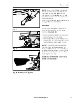
To select a Mitre Angle:
• Loosen the Mitre Angle Locking Screw.
(Fig.12)
This is found at the front RH side
of the table near the 30
0
index mark.
• Turn the Rotary Table to the required
angle. To aid setting, an index mark is
machined into the table just in front of the
table insert.
• Tighten the Mitre Angle Locking Screw
securely when the desired angle has
been selected.
A Mitre Cut can now be made using the
same techniques as previously described in
Chop Cutting.
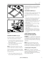
7. Bevel Cutting
The Cutting Head can be set at any angle up
to 45
0
to the Left Hand side only.
The Bevel Locking Lever is found at the
rear of the machine. A protractor guide
and pointer are incorporated into the bevel
mechanism to aid setting.
(Fig.13)
To set a Bevel Angle:
• Loosen the Bevel Lock Handle
• Tilt the Cutting Head to the desired angle.
Use the protractor guide to aid with setting.
• Ensure that the Bevel Lock Handle is
securely tightened when the desired
angle has been achieved.
A Bevel Cut can now be made using the
same techniques as previously outlined.
Fig. 13
Fig. 12
Summary of Contents for Fury 6
Page 2: ...www evolutionfury com 2 03 GB...
Page 29: ...www evolutionfury com 29...
Page 30: ...www evolutionfury com 30...
Page 31: ...www evolutionfury com 31...