Evolution Fury 6 Original Instructions Manual Download Page 14

www.evolutionfury.com

14

GETTING STARTED

WARNING: 

ALWAYS DISCONNECT 

THE SAW FROM THE POWER SOURCE 
BEFORE MAKING ANY ADJUSTMENTS.

Refer to the “Service Parts Diagram”. Install 
a blade as detailed in the “Installing or 
Removing the Blade” section. 

NOTE: 

We recommend that the operator 

reads the 

‘Important Information’ 

sticker 

applied to the table of the Fury6. Practicing 
and becoming familiar with the procedures 
outlined on this sticker will make subsequent 
adjustments/assembly or configuring fairly 
straightforward. 

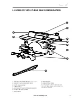
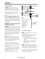
PERMANENTLY MOUNTING THE FURY6 
TABLE/MITRE SAW  (Fig. 1)

WARNING: 

To reduce the risk of injury from 

unexpected saw movement, place the saw 
in the desired location either on a workbench 
or other recommended leg set. The base of 
the saw has four holes to mount the mitre 
saw. If the saw is to be used in one location, 
permanently fasten it to the workbench or 
leg set using appropriate bolts with lock 
washers and nuts.

NOTE:

 When permanently mounting the 

Fury6 we recommend that the four (4) 
rubber feet located underneath each of the 
mounting holes are removed and stored 
safely for possible future use.

1. Tighten the mitre and bevel locks.
2. Position the saw so other people cannot 
stand behind it. Thrown debris could injure 
people in its path.
3. Place the saw on a firm, level surface 
where there is plenty of room for handling 
and properly supporting the workpiece.
4. Support the saw so that the table is level 
and the saw does not rock.
5. Bolt or clamp the saw to its support.

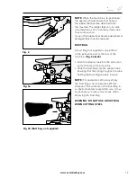
For Portable Use  (Fig. 2)

NOTE:

 The Fury6 is designed to be a highly 

portable machine.
For portable use the Fury6 must be fitted 
with the two (2) rear Stabilising Arms.
To fit the Stabilising Arms:
• 

Remove the cross head machine 
screws from the two (2) rear mounting 
positions.

• 

Attach the Stabilising Arms with the 
machine screws, two per arm and 
tighten securely.

NOTE: 

The Stabilising Arms are fitted with 

rubber feet. The base of the Fury6 is also fitted 
with four (4) identical rubber feet positioned 
underneath the mounting holes in the base.

When used as a portable machine the six (6) 
rubber feet provide the security and stability 
necessary for safe operation.

1) Hex headed bolt M8 X 75 
2) Spring washer  
3) Flat washer  
4) Mitre saw base  
5) Workbench  
6) Flat washer  
7) Spring washer  
8) Hex nut  
9) Lock nut

Fig. 1

9

5

6

7

8

3

4

2

1

THESE ITEMS 
ARE 

NOT 

SUPPLIED

M8 x 75

Summary of Contents for Fury 6

Page 1: ...210mm TCT Multipurpose Mitre Table Saw Original Instructions Read instructions before operating this tool www evolutionfury com 16 04 12_V9...

Page 2: ...www evolutionfury com 2 03 GB...

Page 3: ...imited Warranty 5 General Safety Rules 5 Additional Specific Safety Rules 7 Safety Labels and Symbols 8 Machine Overview 12 13 Operation Mitre Saw 16 Operation Table Saw 21 Maintenance 24 Environmenta...

Page 4: ...hine Directive 2006 95 EC Low Voltage Directive 2004 108 EC EMC Directive 2002 95 EC Restriction of the use of Certain Hazardous Substances in Electrical and Electric Equipment Standards and Technical...

Page 5: ...air or replace it with the same or equivalent item There is no warranty written or verbal for saw blades In no event shall Evolution Power Tools be liable for loss or damage resulting directly or indi...

Page 6: ...t on 17 Avoid unintentional starting Ensure switch is in off position when plugging in 18 Use outdoor extension leads When the tool is used outdoors use only extension cords intended for outdoor use a...

Page 7: ...ion cord be sure to use one that is heavy enough to carry the current that your tool will draw An undersized cord will cause a drop in line voltage resulting in loss of power and overheating 9 Do not...

Page 8: ...safety glasses with side shield and a full face shield when needed WARNING If any parts are missing do not operate your table mitre saw until the missing parts are replaced Failure to follow this rule...

Page 9: ...dition and wear A damaged or worn blade should be replaced immediately Beware of ejecting chips as they may be HOT Always make provision for the safe handling of excess material Keep machine base and...

Page 10: ...epth mm 32 mm Noise and Vibration Data Sound pressure level 106 3dB A K 3dB A Sound power level 119 3dB A K 3dB A Vibration level 2 5 m S2 K 1 5dB A The declared vibration total value has been measure...

Page 11: ...Riving Knife Adjustment 1 Multi Purpose Blade Fitted 1 Rip Fence Bevel Guide Assembly 1 Auxiliary Lower Blade Guard Fitted 1 Dust Bag Adaptor Tube 1 Workpiece Supports 2 Rear Stabilising Arms 2 Addit...

Page 12: ...Y TABLE 3 RETRACTABLE LOWER BLADE GUARD 4 BLADE 5 BEVEL LOCKING LEVER Back of the machine 6 MITRE ANGLE LOCKING SCREW 7 MITRE ANGLE SCALE 8 FENCE 9 HOLD DOWN CLAMP 10 STABILISING ARMS X2 Back of machi...

Page 13: ...TCH Inside handle 2 ON OFF LATCHING SWITCHES 3 CUTTING HANDLE 4 TABLE TOP 5 AUXILLIARY LOWER BLADE GUARD 6 UPPER BLADE GUARD 7 RIP FENCE 8 PUSH STICK 9 MOUNTING HOLE 2 at the front and 2 under the sta...

Page 14: ...nd stored safely for possible future use 1 Tighten the mitre and bevel locks 2 Position the saw so other people cannot stand behind it Thrown debris could injure people in its path 3 Place the saw on...

Page 15: ...he extraction port at the rear of the machine Fig 3a 3b Push the adaptor tube into the extraction port at the rear of the machine Slide the Dust Bag onto the adaptor tube ensuring that the spring clip...

Page 16: ...and acted upon Failure to carry out the configuration procedure could result in damage to the machine and or injury to the operator Loosen the table height adjustment screw Fig 4 Raise the table top t...

Page 17: ...into the socket that best suits the cutting application ensuring that it is pushed fully down Tighten the fence thumbscrew to lock the pillar of the Hold Down Clamp into the fence socket Put the workp...

Page 18: ...m the blade Pictograms on the machines rotary table are provided as an aid to safe working practices Keep hands away from the path of the blade Hold the workpiece firmly to the fence to prevent any mo...

Page 19: ...re provided for every 50 of angular movement Note The rotary table must always be locked into position with the Mitre Angle Locking Screw even if a positive stop is selected To select a Mitre Angle Lo...

Page 20: ...utting Head to check the path of the blade Ensure there is no interference with any other parts of the machine 9 Compound Cutting A Compound Cut is a combination of a Mitre Cut and Bevel Cut Set the M...

Page 21: ...ilure to carry out the configuration procedure could result in damage to the machine and or injury to the operator Ensure that the Rotary Table is set at 00 Mitre angle and the Cutting Head is set at...

Page 22: ...hannel FENCE ASSEMBLY AS A RIP FENCE To use the Fence Assembly as a Rip Fence the Face Plate must be accurately aligned with the blade WARNING Only carry out this procedure with the machine disconnect...

Page 23: ...o minimise the possibility of the blade binding and kickback 1 Adjusting the Table Height Fig 23a 23b The height of the Table above the machines motor can be adjusted This enables your Fury6 to mimic...

Page 24: ...300mm of the material past the blade A Push Stick should always be used when making cuts of less than 300mm Note A Push Stick Fig 25 is provided with the Fury6 and has a dedicated storage position to...

Page 25: ...hen not in use store the push stick on the machine Note If the push stick becomes damaged it should be replaced If the operator makes their own push stick we recommend that it follows the same pattern...

Page 26: ...e Guard The blade teeth should always point downward at the front of the saw Using the blade slot to provide maximum clearance and access to the machine carefully and gently manoeuvre the blade up int...

Page 27: ...Key to turn the Bevel Stop Screw clockwise or counterclockwise as required When exact alignment between the blade and Rotary Table is achieved tighten the locknut 450 BEVEL ANGLE The 450 Bevel Angle c...

Page 28: ...crews FUSE AND PLUG REPLACEMENT Should the fuse in the main plug of your machine need replacing it should always be replaced with one of identical rating Check the voltage given on your machine matche...

Page 29: ...www evolutionfury com 29...

Page 30: ...www evolutionfury com 30...

Page 31: ...www evolutionfury com 31...

Page 32: ...UK ADDRESS Evolution Power Tools Venture One Longacre Close Holbrook Industrial Estate Sheffield S20 3FR TEL 44 0 114 251 1022 FAX 44 0 114 247 3339...

Reviews: