Model 5601MSC
Model 5601MSC Master SPG/Master Clock System
Page - 98
Revision 2.2
MASTER CLOCK
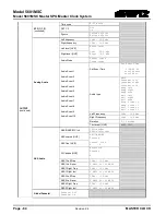
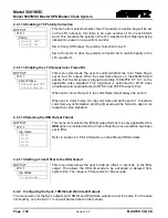
4.4.1. Configuring the LTC Outputs
There are two LTC outputs available on the 5601MSC. Each LTC output has primary outputs on XLR
connectors, and secondary outputs on the GPIO DB15 connector. Each of the outputs can be
individually configured using a similar set of menus. The +12V LTC power is only available on the LTC1
primary output (XLR). This is controlled by the
Power Applied
menu item described in section 4.4.1.1. If
the IRIG option is installed, either of the LTC outputs can be put into IRIG mode. For the sake of
simplicity only the menus for LTC output 1 will be described in the manual.
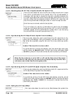
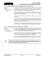
4.4.1.1. Selecting Normal or Powered LTC 1 Output (LTC1 XLR Output Only)
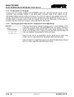
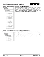
OUTPUT
This menu item controls whether the primary LTC 1 output available on the
3-pin XLR connector will be a standard SMPTE ST 12-1 signal or whether it
will be modulated to drive Evertz 1200 series clocks operating in slave
mode. The secondary LTC 1 output on the 15-pin GPIO connector does not
have the capability of powering the 1200 series clocks.
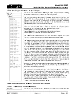
Select
Power Off
for all applications except driving Evertz 1200 series
clocks. The LTC output level is set using the
Output Level
menu item.
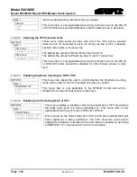
Select
Power On
for applications where you want to transmit power through
the LTC 1 XLR output to Evertz 1200 series clocks.
LTC 1
Power Applied
Power Off
Power On

