


Model 5601MSC
Model 5601MSC Master SPG/Master Clock System
MASTER CLOCK
Revision 2.2
Page - 73
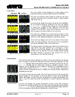
Lock status
Unlocked
→
Locked
[#1]
10MHz frequency ref, no time ref
[#2]
GPS frequency ref, GPS time ref
[#3]
No frequency ref, Modem time ref
[#4]
Video frequency ref, VITC time ref
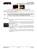
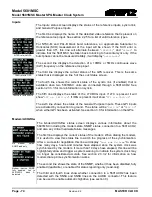
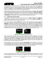
The
Lock Status
screen displays the current status of the
selected frequency and time references for the 5601MSC.
The first line indicates which frequency reference has been
selected, and if the unit is using the narrow or wide oscillator
(see section 2.2.3).
The second line shows the overall lock status of the 5601MSC
to the selected frequency reference. This line will display
“
Lock progrs x%
” while locking to show the current progress
in locking the oscillator to the reference. This line also
indicates if the 5601MSC has locked to frequency only, or has
both frequency and phase locked to the reference.
The third line indicates the current tuning position of the
selected oscillator when locked to the reference. See section
2.2.3 for a more detailed explanation on what this means.
The fourth line displays the current lock status of the system
clock to the time reference. See section 0 for an explanation
on how the 5601MSC locks to time references.
The fifth and sixth lines display the status of the GPS receiver
when GPS has been selected as a frequency or time
reference. The fifth line displays the current GPS lock state,
and the sixth line displays how many healthy satellite signals
the GPS antenna is receiving. See section 2.5.2 for an
explanation on the GPS lock process.
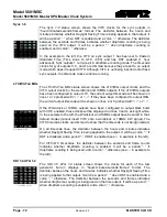
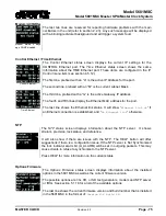
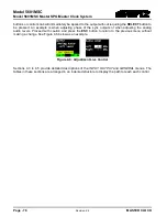
Fan/PS status
Dual power supplies
Single power supply
The
Fan/PS status
screen displays the status of the power supplies and exhaust
fans at a glance. The first line indicates the status of the power supplies. The text
“
PS L Ok
” indicates that the left power supply is operating normally and the text
“
PS R Ok
” indicates that the right power supply is operating normally. These
statuses will be highlighted red if a failure is detected. For installations with a
single power supply, the text “
Power Supply OK
” will be shown. See section
4.5.9.5 for more information on how to configure the number of power supplies the
5601MSC will monitor.
The next four lines show the status of the front and rear fans for the left and right
power supplies (or fan modules). If a fan has failed, the line will be highlighted
yellow and trigger a system warning. Depending on ambient temperature, this
may or may not cause the system temperature to exceed maximum operating
levels.
The last line displays the system temperature monitor. If the main processor
temperature exceeds operating limits, this line will be highlighted red and indicate
“
Temp too high
”. This is a critical system fault and required immediate attention.
It can be caused by high ambient temperatures or by fan failures.