background image

NAV Series TCP/IP Standalone Network Access Controller 


56 


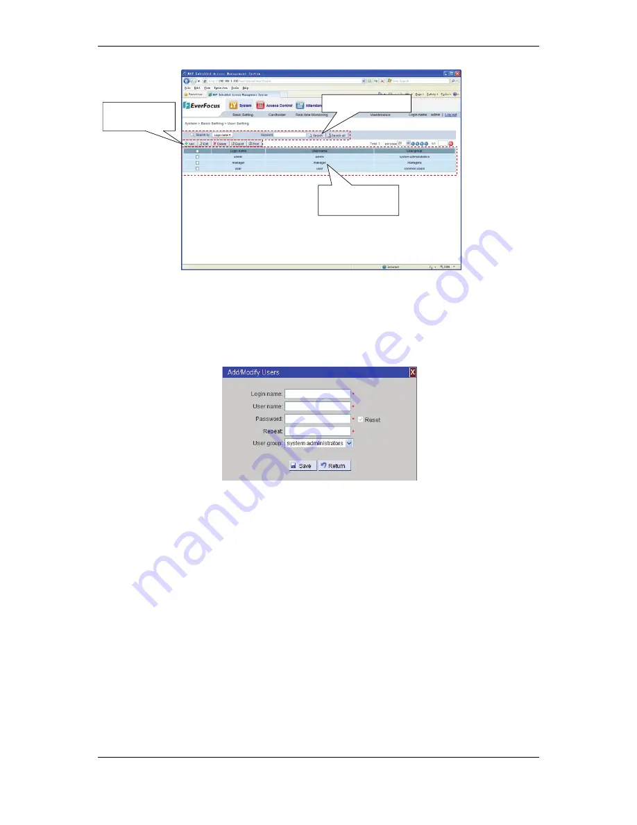
Figure 7-4 User Setting 


7.4.1 Add User 

In


the


page,


click


the


“Add”


button


in


“Function


Editing


Region,”


then


the


user


addition


page


pops


up


(see


Figure


7

5).


Input


the


login


name,


username,


password


and


User


Group


name


and


click


the


“Save”


button


to


add


a


new


user


to


the


user


list


in


the


page.


Figure 7-5 Add user 


Login


name:


The


name


for


the


user


to


log


in


and


use


the


software,


which


can


be


any


combination


of


figures,


letters,


spaces,


Chinese


characters


and


other


displayable


characters.


The


longest


login


name


is


20


bits


and


any


character


occupies


1


bit.


The


letters


of


the


login


name


are


case


sensitive.


The


login


name


cannot


be


the


same


as


an


existing


user


login


name


and


cannot


be


empty.


If


the


user


inputs


an


existing


login


name,


the


system


will


prompt


that


the


login


name


has


already


been


used


when


saving


it.


Username:


The


true


name


of


user.


This


item


is


for


facilitating


system


management


and


must


be


filled


in.


Password

:


Any


combination


of


figures,


letters,


spaces,


Chinese


characters


and


other


displayable


characters.


The


longest


login


name


is


20


bits


and


any


character


occupies


1


bit.


The


letters


of


the


login


name


are


case


sensitive.


Confirm


password:


Must


be


the


same


as


the


input


content


of


the


password.


If


the


two


passwords


input


are


not


consistent


with


each


other,


the


system


will


prompt


that


“Input


Password


Do


Not


Match.”


Name


of


User


Group:


Name


of


the


User


Group


to


which


the


user


belongs.


The


administrator


can


allocate


the


new


user


to


any


User


Group


and


the


User


Group


of


the


system


administrator


can


operate


all


functional


modules.


User Query Region 

Function 
Editing Region 

User Information 
Region 

Summary of Contents for EFC301

Page 1: ...User Manual EFC301 NAV Series TCP IP Standalone Network Access Controller Volume 2...

Page 2: ...nstruction Guide 2011 2012 EverFocus Electronics Corp All rights reserved No part of the contents of this manual may be reproduced or transmitted in any form or by any means without written permission...

Page 3: ...2 2 1 Installing The Controller 8 2 2 2 Connecting To The Door Lock Sensor Open Button 9 2 2 3 Connecting To The Alarm Input Output 11 2 2 4 Connecting To The Computer Through The Network 12 3 Startin...

Page 4: ...35 4 7 8 Ip Address Setting 35 4 7 9 Reset Network Setting 36 4 8 System Info 36 4 9 Introduction Of System Operation 36 4 9 1 Door Open By Swiping Card 36 4 9 2 Door Open With Single Password 36 4 9...

Page 5: ...e User Group 55 7 4 User Setting 55 7 4 1 Add User 56 7 4 2 Edit User 57 7 4 3 Delete User 57 7 4 4 Export User Information 57 7 4 5 Print User Information 57 7 4 6 Search User 57 7 5 Local Server 58...

Page 6: ...nagement 75 11 1 Controller Setting 75 11 1 1 Change Controller Information 75 12 Access Rule 77 12 1 Date Type 77 12 1 1 Add Date 77 12 1 2 Delete Date 78 12 2 Door Schedule 78 12 3 Group Schedule 80...

Page 7: ...1 Attendence Time Setting 93 15 2 Edit Attendence Time 93 15 2 1 Query Attendance Time 94 15 2 2 Export Attendance Information 94 15 2 3 Print Attendance Information 94 15 3 Week Holiday Setting 94 15...

Page 8: ...106 16 3 5 Export Overtime Enroll Records 106 16 3 6 Print Overtime Enroll Record 106 17 Attendance Report 107 17 1 Original Access Record 107 17 1 1 Query Original Access Record 107 17 1 2 Export Ori...

Page 9: ...he controller Figure 1 1 1 1 Features Network access through CAT 5 cable 10M 100M Ethernet or PoE Remote setting control and management no software needed to be installed Secure access through the Web...

Page 10: ...Interface 10 100M adaptive Ethernet interface Card Reading Distance 5 10 cm Card Reading Time 200 ms Programmable Time Periods Each day can be divided into 10 time period with a minimum time interval...

Page 11: ...any items appear to have been damaged in the shipping process If any items are missing notify your EverFocus Electronics Corp Sales Representative or Customer Service Branch Please also keep the ship...

Page 12: ...Blue Alarm NO Alarm output normally opened terminal 9 Yellow Door Button Door open button 10 White Door NC Door lock output normally closed terminal 11 Orange Comm GND Common terminal of door status...

Page 13: ...lid 3 Yellow When light is constantly on it indicates the door lock is opened When light is constantly in the protection setup statue it indicates the protection setup success When blink slowly it ind...

Page 14: ...installed Obtaining a floor plan helps the installer determine what components need to be installed Chapter 2 Step 1 Installation Preparation Obtain a floor plan Determine the hardware and location De...

Page 15: ...urces These resources include but are not limited to proximity readers mag strip readers relays and request to exits A few common door configurations are described below One Set of EFC301 The Basic Do...

Page 16: ...he alarm input output 4 Connecting to the computer through the network 2 2 1 Installing the Controller The controller should be installed in an easily accessible position However it should be noticed...

Page 17: ...Each controller provides the interface of the door control relay corresponding to the No 10 12 and 14 output extension wires on the back plate of the controller The No 12 extension wire is a common te...

Page 18: ...n be optionally connected Figure 2 5 Note The maximum output current of the relay on the controller is smaller than 4A If the current of the door lock is over this value the relay will be expanded 2 2...

Page 19: ...n wire on the back plate of the controller and the ground terminal is connected with the No 11 extension wire Figure 2 7 2 2 3 Connecting to the Alarm Input Output 2 2 3 1 Connecting to the Fire Alarm...

Page 20: ...minal normally opened terminal and normally closed terminal The wire connection should be determined according to the alarm Before wire connection please read the instructions of the external alarm Th...

Page 21: ...ller is DC 11 16V The maximum current of the controller is 600mA 2 The distance from the power supply to the controller should be minimal In addition the electromagnetic lock and alarm equipment must...

Page 22: ...CP IP Standalone Network Access Controller 14 1 Reset the controller 2 Set up the IP address date and time of the controller 3 Set up the alarm signals 4 Set up the door settings 5 Set up the date and...

Page 23: ...2 3 4 5 6 7 8 9 0 The 3 4 keyboard on the main card reader is shown in the figure above Main Interface System function key Protection setup withdrawal key Enter System Menu OK Cancel 2 8 Up and down m...

Page 24: ...following screen will show up Press on the main interface of the system and the protection setup withdrawal administration Interface will show up First the system requests that the user input the alar...

Page 25: ...ntroller will indicate four different states see Table 4 1 Table 4 1 States of Indicator Lamp Yellow LED System Protection State Off In protection withdrawal state On In protection setup state Slowly...

Page 26: ...he numerical keys 2 and 8 to select the menu items and press to enter the corresponding setup 4 4 1 Set Language In the System Setting menu scroll to Set Language menu item and press to enter the Set...

Page 27: ...exit the data display format setup interface And return to the System Setting menu 4 4 3 Set Date In the System Setting menu scroll to Set Date menu item and press to enter the Set Date interface Use...

Page 28: ...Daylight interface Press to toggle between summer time on off and press to exit The setting is finalized upon exit When the summer time setting is enabled the controller will automatically adjust to...

Page 29: ...l display whether the new password takes effect If the two passwords entered are different the system will prompt to reset Pressing before pressing for confirmation the new password will not take effe...

Page 30: ...ds All event records can be cleared through the following instructions In the System Setting menu scroll to the Erase All Events menu item and press to enter the Erase All Events interface The system...

Page 31: ...the backlight that will be on for every keystroke operation or card swiping If there is no subsequent operation the backlight will turn off after 1 min Press to exit The setting will be finalized on e...

Page 32: ...ion setups under the Card Setting menu will be introduced below 4 5 1 Add Card In the Card Setting submenu scroll to Add Card menu item and press to enter the Add Card interface When adding a card the...

Page 33: ...ller can delete one card through its card number The card number corresponding to the card to be deleted has to be inputted manually or by swiping the card In the Delete Card submenu scroll to the Del...

Page 34: ...em and press to enter the Set Card Properties interface The system will prompt the user to input the card number If the card does not exist in the system the system will prompt Unknown Card After inpu...

Page 35: ...tting is finalized upon exit If a card is set to open the administrator function the card holder will be assigned as the system administrator If there are one or more cards with administrator authorit...

Page 36: ...card function at the controller terminal will trigger the door normal open setting in the Access Access Rule this setting is involved in the Access Control regulation rules in the embedded software of...

Page 37: ...be changed Scroll to the Modify PIN menu item and press to enter its interface The system will prompt the user to input a new card password After inputting press to confirm then the system will prompt...

Page 38: ...he range of 0 999 and for setting seconds input two digits in the range of 0 59 Press to confirm and the setting will take effect Press to exit and the setting will not take effect 4 6 2 Set Over Time...

Page 39: ...rd all events such as entry permit entry prohibition etc Some dangerous events are required to trigger alarm output such as fire alarm input protection area alarm input etc Some events do not need ala...

Page 40: ...input signal is in the off state under the normal state no input and the on state of the input indicates the input of an alarm signal On the contrary the Normally Off mode indicates that the input sig...

Page 41: ...ected the alarm output and alarm input will occur and be withdrawn simultaneously After selecting the input and output modes press to save the current settings and enter the protection setup delay tim...

Page 42: ...ing alarm events and Alarm Action Setting for the corresponding events For example in case of setting the SYS PIN Fail in the submenu scroll to the SYS PIN Fail menu item and press to enter the alarm...

Page 43: ...HCP Setting Scroll to the DHCP Setting menu item and press function key or numerical keys 5 or 6 to enter the setting menu Press key to switch between ON and OFF Press to confirm the DHCP status setti...

Page 44: ...ntroduction of System Operation 4 9 1 Door Open by Swiping Card If the swiped card has the corresponding user name after successful authentication the user name information of the card holder and Auth...

Page 45: ...ining time If the system receives the next legal card before the end of the time the system will display a message of user information and successful authentication and last 3 seconds and then open th...

Page 46: ...en the door after verifying a card with the first card authority and keep the door lock in the unlocked state In the event that the door is opened without the first card the system will directly unloc...

Page 47: ...database is encrypted to avoid illegal access to the database Users can be granted with authority capable of distinguishing the Cardholder logged in and the users divided into different User Groups u...

Page 48: ...the administrator can more visually know the current status and discover and solve the problem in time Supports remote operation of the controller door region protection region alarm etc Supports dure...

Page 49: ...Access Rule Door Region Scheme Settings to enter the interface of door region scheme settings Following are instructions for how to add a door region design for detailed settings please refer to page...

Page 50: ...and allocate it into the corresponding control group The default control group is Full Granted and the default password is 000000 First select the format of the card to be added 6 1 2 1 Rapid Card Ad...

Page 51: ...ted and click Next 2 Select the corresponding value of the related column name 3 Click the Import button to finish the addition 6 1 3 Set Department and Cardholder 6 1 3 1 Set Department Click the men...

Page 52: ...on 6 1 4 3 Overtime Enroll Click the menu bar Attendance Attendance Exception Overtime Enroll to enter the page Following are instructions for how to register overtime for detailed settings please ref...

Page 53: ...the pa F k the Save s are includ with Excel the file con llowing pro and select with notep ee the figure NAV S 45 ge is the de m provide a mation in th re below gure 6 1 Exp ath to save t Figure 6 2...

Page 54: ...con e with Exce he system p page see Fig Tree Go to Close Curr of printing Figure 6 4 IP address r the IP add he prompts e Login bu ntroller 46 3 Convert exp s Save type version el and chec provide Pr...

Page 55: ...passwo r and then d is wrong Figu with the the Main d design co NAV S 47 igure 6 5 Log ge at the rig Russian lan EFC301 con ministrator r administra itself can n ber well the r is carried nistrator ca...

Page 56: ...unctions will be introduced in detail in the latter chapters Figure 6 8 Menu bar If a login user has no access authority to a certain module function the function will not be displayed on the menu bar...

Page 57: ...e region displays all the event records of the system including normal card swiping records illegal card swiping records operation control records alarm records etc 6 3 4 1 Entry Exit Card Swiping Rec...

Page 58: ...cords of the remote operation of the controller in the software the records of protection setup withdrawal on the controller the records of restore alarm the records of door open with the door open bu...

Page 59: ...troller 51 Figure 6 14 Alarm event records 6 3 4 5 Other Records The other records related to the controller in the system include events lost The content of system settings records includes event tim...

Page 60: ...eway date time etc of NAV controller System upgrade Support online upgrade and local upgrade Central server configuration Configure the address password etc of the ENS2000 NAV Series Web IP based Acce...

Page 61: ...System Basic Setting User Group to enter the User Group page For detailed settings please refer to Page 54 7 3User Group When entering the User Group in case of first use of the software the system wi...

Page 62: ...Attendance Time off Enroll Overtime Enroll Original Access Record Report by Cardholder Statistics by Cardholder Statistics by Department CCTV DVR settings Single view settings Table 7 1 Function list...

Page 63: ...side User Group list click the Delete button then the confirmation dialog box Confirm Delete pops up If it is confirmed to delete the User Group click the OK button then the system displays a dialog b...

Page 64: ...ot be empty If the user inputs an existing login name the system will prompt that the login name has already been used when saving it Username The true name of user This item is for facilitating syste...

Page 65: ...e operation Note The default user admin cannot be deleted 7 4 4 Export User Information Click the Export button to export all user information in the system in the csv format then the file save dialog...

Page 66: ...as in the above figure select static or dynamic type input IP subnet mask and gateway in the textbox confirm and click the OK button The page will display this prompt dialog box Click OK again and re...

Page 67: ...tem upgrade page See Figure 7 9 By default the online upgrade page will show up Figure 7 9 Online upgrade 7 6 1 Online Upgrade The upgrade is carried out through the FTP or HTTP address and account pr...

Page 68: ...NAV Series TCP IP Standalone Network Access Controller 60 Figure 7 10 Local upgrade...

Page 69: ...nt Setting to enter the page of department setting see the figure below Figure 8 1 Department setting The left side of the page is the tree structure of the organization structure and the right side o...

Page 70: ...age see the figure below Figure 8 3 Change department Input the name of the department in the input box of Department Name click the input box of Superior Department select the superior department to...

Page 71: ...middle line is the operation region and the lower part is the Cardholder information list In the operation region on the right upper corner of the page the number of Cardholder information items disp...

Page 72: ...r information Name True name of Cardholder Gender The gender is male by default Department Click the department to which the new Cardholder member belongs Employment Resignation date When clicking the...

Page 73: ...he card One user can hold one or more cards Figure 8 11 Card repeat Delete Card Select the tab of the card to be deleted click the Delete Card button to delete the card Note This operation is real tim...

Page 74: ...f the three rules of the card the order of priority is Card design Control group scheme door design with the priority from high to low The design selected from the pull down menu of the card design is...

Page 75: ...ures please refer to page 45 6 1 6 Export Function 8 2 5 Print Cardholder Information Click the Print button to enter the user information printing page For detailed operation procedures please refer...

Page 76: ...e 8 15 Import Cardholder information 3 Click the drop down box of each attribute select the corresponding attribute category and check the radio button at the top of the column 4 Click the Import butt...

Page 77: ...ot etc The real time event records of the controller are positioned in the middle part It automatically receives the event information of the controller and scrolls the event information to display in...

Page 78: ...ting the condition Click the All button and the system will list all Cardholder information in the system For example employee numbers ef 001 and ef 002 are available in the system If you want to quer...

Page 79: ...r the data backup page see the figure below Figure 10 1 Data backup 10 1 1 Manual Backup Manual backup refers to backup of system data in the local server through the operation of the administrator Se...

Page 80: ...and start time of automatic backup 3 Set the username password URL port and file save path of the backup file in the FTP server FTP server refers to remote server 4 Select whether the expired backup...

Page 81: ...ton 10 2 2 Restore from Local Figure 10 5 Restore from Local Operation Procedures 1 Click the Browse button and select the site for saving the restored file locally 2 Select the file to be restored an...

Page 82: ...ording to the selection time For example select the Remote Door Open events occurring 3 months ago and Click the Clear button then the system will delete all the Remote Door Open events occurring 3 mo...

Page 83: ...e provided in this operation page of the controller see Figure 12 1 card reader alarm alarm time or other settings Next the operations will be introduced in detail 11 1 1 1 Door Region Setting In the...

Page 84: ...d reader is in door entry position or door exit position If the item is checked it indicates that the card reader is in the door exit position After inputting the waiting time in the card reader infor...

Page 85: ...g of 10 date types including from Sunday to Saturday 7 types user defined 1 user defined 1 and user defined 3 of which Sunday to Saturday are automatically set according to the calendar and user can d...

Page 86: ...ery year The user need not change the week holiday every year Note These holidays should be allocated during system initialization and re checked at the beginning of every year Operation Procedures 1...

Page 87: ...n and select the respective locking level of the four locks in the lock level column In the control group setting page the corresponding unlocking level of the card can be set After setting and changi...

Page 88: ...p Schedule In the control group scheme setting page click the Add button to enter the scheme setting page Figure 12 7 Add control group scheme Operation Procedures 1 Input the name of a new design in...

Page 89: ...me periods allow free entry exit In case it is required to respectively set the date time periods in the schemes in the control scheme setting page left click Date Setting in the selected date type th...

Page 90: ...oup scheme can be changed and saved as an original scheme or saved as new scheme This function helps the user to rapidly add some control group schemes with similar scheme contents Operation Procedure...

Page 91: ...3 Select the name of the control group scheme or the door scheme 4 Click the Save button to finish control group adding Click the Scheme button then the page will switch to the control group scheme pa...

Page 92: ...card setting page is comprised of the upper query operation region the operating button region and the lower card list column Query operation region Select query conditions and keywords to conduct a p...

Page 93: ...play the Cardholder number click to select In a similar way the Cardholder number can be input first 4 After selecting the attributes of the card click the Save button then the card will be added to t...

Page 94: ...rogress bar reaches 100 Then the dialog box disappears Figure 13 6 Change card 13 1 3 Change Cards in Batch Press Shift on the keyboard while selecting multiple cards click the Edit button change the...

Page 95: ...save the file and click OK For detailed operation procedures please refer to page 45 6 1 6 Export Function 13 1 7 Print Card Information Click the Print button to enter the card information printing p...

Page 96: ...e The size of the imported csv file should be not more than 1Mb If the format of the file is correctly selected the following page will be switched to Figure 13 8 Card import Check the column number o...

Page 97: ...NAV Series TCP IP Standalone Network Access Controller 89 Figure 13 9 Error occurred during card import Click the Return button to return to the file selection page to reset...

Page 98: ...nd control group 2 Input keywords in the textbox 3 Click the Query button then the controller will display all the card information meeting the condition in the list column below 4 If you want to view...

Page 99: ...tion in the list column below 4 If you want to view all the card information in the current controller click the All button 14 2 2 Import Card Related Events Click the Export button to export all the...

Page 100: ...rd information in the current controller click the All button 14 3 2 Import Card Irrelevant Events Click the Export button to export all the card irrelevant events in the system in the csv format then...

Page 101: ...list The attendance statistics cannot be finished until the attendance time is correctly set 15 2 Edit Attendence Time Set the departmental attendance time for the first time or reset the departmental...

Page 102: ...ttendance Information Click the Export button to export all Attendance information in the system in the csv format then the file save dialog box pops up Select the path to save the file and click OK F...

Page 103: ...for the first time or reset the departmental weekends Select one record to be set in the list click the Edit button to enter the setting page of the weekend of the appointed department correctly set...

Page 104: ...page 45 6 1 6 Export Function 15 3 4 Print Weekend Click the Print button to enter the weekend information printing page For detailed operation procedures please refer to page 46 6 1 7Print Function 1...

Page 105: ...Settings Select the department to be queried Default is all departments Select query time range Default is the current month Click the Query button then the list of special dates meeting the condition...

Page 106: ...system shows a prompt reading Deleted successfully indicating the deletion is successful 15 4 5 Export Special Date Click the Export button to export all the special date information in the system in...

Page 107: ...6 1 Figure 16 1 No Access Attendance 16 1 1 Add No Access Attendance Click the Add button to enter the registration page of not swiping a card select one record in the Cardholder list set card swiping...

Page 108: ...y default the system returns all the registration records of not swiping a card in the current month see Figure 16 3 The user can set query time range and input the employee number or name of the Card...

Page 109: ...leted successfully it indicates that the deletion is successful and this record does not exist in the system any more 16 1 5 Export Registration of Not Swiping a card Click the Export button to export...

Page 110: ...Time off Enroll list You can see the new leave record has been added successfully Figure 16 6 Add Time off Enroll If it is not convenient to search in the user you can directly input the employee num...

Page 111: ...ed click the Save button After the system prompts Changed successfully click the Return button You can see that the leave duration in this record has been changed 16 2 4 Delete Leave Record If there i...

Page 112: ...ember works overtime the Overtime Enroll must be added to ensure the correctness of the Attendance statistical data Click the Attendance Attendance Exception Overtime Enroll then the system enters the...

Page 113: ...t the system returns all the Overtime Enroll records in the current month The user can set the query time range and input the employee number or name of the Cardholder to be queried to realize a preci...

Page 114: ...x pops up If it is confirmed click the OK button If the system displays prompt information reading Deleted successfully it indicates that the deletion is successful and this record does not exist in t...

Page 115: ...ime of the card swiping records to be queried 4 Click the Query button then the information meeting the conditions will be displayed in the card swiping record list below 17 1 2 Export Original Access...

Page 116: ...the information meeting the condition will be displayed in the record list below 17 2 2 Export Report by Cardholder Click the Export button to export all the Attendance reports or queried Attendance...

Page 117: ...k the Export button to export all the Attendance reports or queried Attendance records of one Cardholder in the system in the csv format then the file save dialog box pops up Select the path to save t...

Page 118: ...f the Statistics by Department 3 If you want to query the Original Access Record of a Cardholder input the employee number of the Cardholder If you want to query the card swiping records of all Cardho...

Page 119: ...r 111 procedures please refer to page 45 6 1 6 Export Function 17 4 3 Print Statistics by Department Click the Print button to enter the Statistics by Department printing page For detailed operation p...

Page 120: ...WBG Marive East 18F 2 6 Nakase Mihama ku Chiba city 261 7118 Japan Tel 81 43 212 8188 Fax 81 43 297 0081 European Office Albert Einstein Strasse 1 D 46446 Emmerich German Tel 49 2822 9394 0 Fax 49 28...

Reviews: