


Operating the Converter
4-5
590+ Series DC Digital Converter
Microtach/Encoder Feedback Option Board
The option board assumes a 1000 lines per rev encoder is being used. Speed is set directly by the
ENCODER RPM parameter. If you are using an alternative lines per rev encoder, you must set
the ENCODER LINES parameter on the Operator Station later in the Operating Instructions.
Note the CONFIGURE DRIVE menu at the top of the menu tree which contains many of
the important parameters used during set-up.
Refer to Chapter 5: “The Operator Station” to familiarise yourself with the Operator
Station’s LED indications, and how to use the keys and menu structure.
Calibration
AUXILIARY POWER ONLY IS CONNECTED AT THIS STAGE
Connect the auxiliary power supply to auxiliary supply terminals L & N (but do not connect the
main 3-phase power supply at this stage). Check that the correct voltage appears between these
terminals.
The Operator Station will now display the Welcome screen, and the Health and Overcurrent Trip
Operator Station LEDs will be illuminated (assuming that the Converter’s control terminals are
wired as shown in Figure 3-4, Minimum Connection Requirements).
You must first calibrate the Converter for use with the motor.
IMPORTANT:
You must not exceed the maximum drive and motor ratings. Refer to the Product Code or
maximum rating label, and the motor rating plate.
Set the following parameters, but first select CONFIGURE ENABLE to be ENABLED.
FLD.CTRL MODE
Set the field control mode to Field Voltage or Field Current control. Refer to Chapter 6:
“Programming Your Application” - Field Control for further information. By default, the drive is
operating in Voltage Control mode.
FLD.VOLTS RATIO
Enter the calculated ratio into the parameter given by the equation:
The default setting of 90% is the maximum value obtainable,
i.e. field output = 0.9 x Vac
Calibrating for Frames 1 & 2
AUXILIARY POWER ONLY IS CONNECTED AT THIS STAGE
NOM MOTOR VOLTS – Armature Voltage (VACAL)
If the drive’s nominal power supply voltage is 220V, set DOUBLE
the Armature Voltage value in the Configure Drive menu.
OR
If the drive’s nominal power supply voltage is 500V, set the Armature Voltage value in the
Configure Drive menu.
ARMATURE CURRENT (IA CAL)
Note the maximum armature current from the motor rating plate and
set this value in the ARMATURE CURRENT parameter.
FIELD CURRENT (IF CAL)
Note the nominal field current from the motor rating plate and set this
value in the FIELD CURRENT parameter.
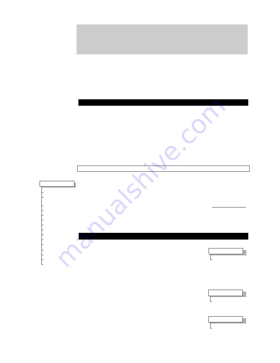
MMI Menu Map
1
CONFIGURE DRIVE
CONFIGURE ENABLE
NOM MOTOR VOLTS
ARMATURE
CURRENT
FIELD CURRENT
ZERO CAL INPUTS
FLD.CTRL MODE
FLD.VOLTS RATIO
CUR.LIMIT/SCALER
AUTOTUNE
SPEED FBK SELECT
ENCODER LINES
ENCODER RPM
ENCODER SIGN
SPD.INT.TIME
SPD.PROP.GAIN
FIELD VOLTS
RMS AC INPUT VOLTS
100 x
MMI Menu Map
1
CONFIGURE DRIVE
NOM MOTOR VOLTS
MMI Menu Map
1
CONFIGURE DRIVE
ARMATURE CURRENT
MMI Menu Map
1
CONFIGURE DRIVE
FIELD CURRENT
Summary of Contents for 590+ Series
Page 16: ...1 4 Getting Started 590 Series DC Digital Converter ...
Page 76: ...3 50 Installing the Converter 590 Series DC Digital Converter ...
Page 110: ...5 14 The Operator Station 590 Series DC Digital Converter ...
Page 194: ...7 10 Trips and Fault Finding 590 Series DC Digital Converter ...
Page 208: ...9 6 Control Loops 590 Series DC Digital Converter ...
Page 236: ...10 28 Parameter Specification Table 590 Series DC Digital Converter ...
Page 260: ...11 24 Technical Specifications 590 Series DC Digital Converter ...
Page 274: ...12 14 Certification for the Converter 590 Series DC Digital Converter ...
Page 300: ...15 2 The Default Application 590 Series DC Digital Converter ...
Page 308: ......