


Control Loops
9-3
590+ Series DC Digital Converter
Subsequently either
•
a squarewave signal should be applied to the current demand input (Terminal A3) with
Current Demand Isolate (terminal C8) on
•
or "toggle" between two values of current limit into terminal A6 and operate in normal speed
loop mode.
Ideally this input signal should be offset above the Discontinuous level, such that the drive is
operating in the continuous current region. Then you could increase the value of I gain to give a
fast rise with no more than 10% overshoot and subsequently increase the P gain towards
critically damped response, i.e. practically no overshoot.
Tuning Hints
If the I gain is too high, the response will be underdamped (overshoot will be excessive with long
oscillatory settling). If the I gain is too low, the response will be overdamped (long exponential
rise).
With the I gain optimally set, if the P gain is too low the response will be overdamped. If P is too
high the response will revert to underdamped with the tendency to go totally unstable.
Diagnostics
The diagnostic point for "real" armature current is the first (left-hand side) test point below the
calibration panel. This will give 1.1V average for 100% current. It will also give the operating
bridge, i.e. it will be negative for the Master bridge (positive current demand) and positive for
the Slave bridge (negative current demand).
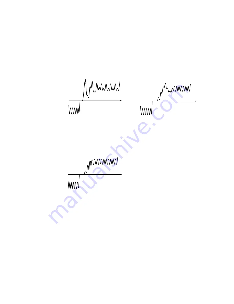
Current Loop controls incorrectly set.
Proportional Gain too low - increase
Current Loop Proportional Gain
8
Current Loop controls incorrectly set.
Integral Time Constant too short
increase Current Loop Integral Time
Constant
8
Current Loop response
correctly adjusted.
9
Summary of Contents for 590+ Series
Page 16: ...1 4 Getting Started 590 Series DC Digital Converter ...
Page 76: ...3 50 Installing the Converter 590 Series DC Digital Converter ...
Page 110: ...5 14 The Operator Station 590 Series DC Digital Converter ...
Page 194: ...7 10 Trips and Fault Finding 590 Series DC Digital Converter ...
Page 208: ...9 6 Control Loops 590 Series DC Digital Converter ...
Page 236: ...10 28 Parameter Specification Table 590 Series DC Digital Converter ...
Page 260: ...11 24 Technical Specifications 590 Series DC Digital Converter ...
Page 274: ...12 14 Certification for the Converter 590 Series DC Digital Converter ...
Page 300: ...15 2 The Default Application 590 Series DC Digital Converter ...
Page 308: ......