background image

Irideon Control Installation and User Manual

31

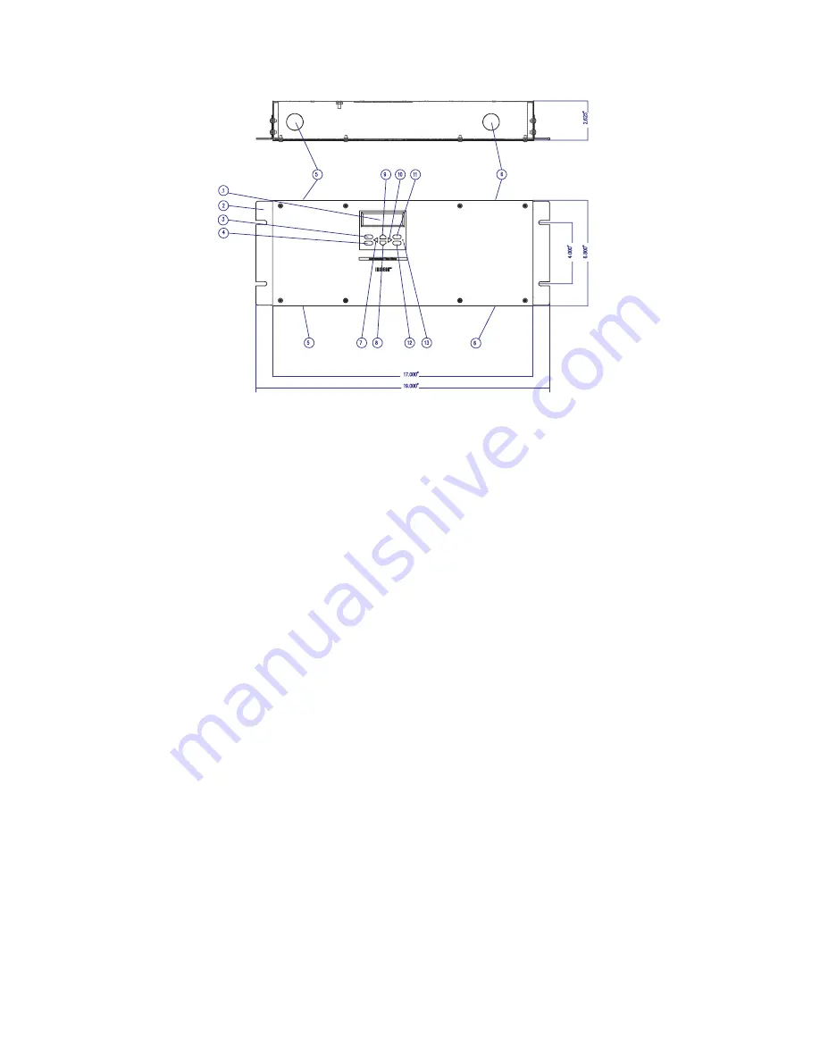
Astronomical Time Clock (ATC)- detail

1. Astronomical Time Clock display.

2. Mounting Bracket - for rack mounting.

3. Review - key used during programming for review of programmed 

steps.

4. Run - key used during programming to return the control to RUN 

mode.

5. Knock-Outs - manufacturer provided knock-outs for easy wiring 

access.

6. Knock-Outs - manufacturer provided knock-outs for easy wiring 

access.

7. (+) - key used during programming to decrement a current flashing 

item.

8. Next - key used during programming to move the display to the 

next program step.

9. Previous - key used during programming to move the display to 

the previous program step.

10. (-) - key used during programming to increment a current flashing 

item.

11. Program - key used during programming to add, delete, or change 

parameters.

12. Override - key used during programming, takes the user to the 

override header.

13. Master Reset - clears time and program

Summary of Contents for IRIDEON

Page 1: ...ol Installation and User Manual Revision B Copyright Electronic Theatre Controls Inc All Rights reserved Product information and specifications subject to change Part Number 7090M1008 Rev B Released 1...

Page 2: ...ng Designs are registered trademarks owned by Electronic Theatre Controls Inc 3030 Laura Lane Middleton Wisconsin USA registered in the United States and other countries Microsoft and Windows are regi...

Page 3: ...Power and Control Cabling for Irideon Control System 17 Installation Procedure 18 Master Control Processor MCP 18 Astronomical Time Clock ATC 20 Remote Control Stations 23 Composer Lite 25 Luminaire P...

Page 4: ...omponents 58 Appendix B Astronomical Time Clock installation instructions 61 Astronomical Time Clock ATC installation instructions for existing MCP Remote Station installations 62 Installation of the...

Page 5: ...ion and operation of the Irideon control system It is designed to be used in conjunction with the existing luminaire owners manual for the specific luminaire type you are using The introduction contai...

Page 6: ...ed descriptions of the Composer Hardware components such as the MCP ATC Remote Stations or the automated lighting fixtures themselves Refer to the associated user manuals for additional information on...

Page 7: ...and field maintenance procedures including lamp replacement Maintenance The ETC Irideon Control System is designed for maintenance free operation In the event problems do occur please contact your lo...

Page 8: ..._____Fax ______________ Technical Support If none of these resources is sufficient contact ETC Technical Support hours of operation are 8 00 AM to 5 00 PM Central time Monday through Friday If you cal...

Page 9: ...608 831 4116 service etcconnect com Europe ETC Europe Ltd Technical Services Department 5 Victoria Industrial Estate Victoria Road London W3 6UU England 44 0 20 8896 1000 service etceurope com Asia ET...

Page 10: ...6 Introduction This page intentionally blank...

Page 11: ...rchitectural lighting control system is designed to maximize the full potential of Irideon multi parameter luminaires This chapter contains the following sections Irideon Control System Options 8 Comp...

Page 12: ...poser Software and a Maser Control Processor MCP Optional controls for this system type may include Remote Control Stations and the Irideon Astronomical Time Clock ATC A simpler less complex control s...

Page 13: ...rol Processor MCP via serial extension cable to a DB9 connector located on the front panel of the MCP or connected to the MCP remotely via MCP Remote Programming Receptacle station The PC can download...

Page 14: ...sor MCP Acts as a remote CPU for the control system The MCP can receive downloaded preset and sequence data from the PC via a DB9 receptacle located on the front panel of the MCP or from an MCP Remote...

Page 15: ...tegral LED for visual indication of the activated event Preset recall Sequence activation Zone control User definable buttons Multiple templates Security Key switch station KS Station used to disable...

Page 16: ...ser Lite Programming kit Remote control stations are not compatible with Composer Lite systems Personal Computer PC not provided by ETC Used to define all programmed actions including presets and sequ...

Page 17: ...atures of Composer Lite Software Intuitive graphic user interface Low cost automated luminaire control Controls a maximum of 31 Irideon luminaires Single sequence operation with up to 30 presets Lumin...

Page 18: ...tible with the DMX Interpreter Features of the DMX Interpreter Rack or Wall mount 100 240VAC operating voltage Front panel status indication On board test diagnostics Non volatile memory Auto reset af...

Page 19: ...Irideon Control System17 Installation Procedure 18 Master Control Processor MCP 18 Astronomical Time Clock ATC 20 Remote Control Stations 23 Composer Lite 25 Luminaire Programming Jack LPJ 26 DMX Int...

Page 20: ...length of daisy chained cable runs Recommended maximum overall cable length for each data run and remote control run cannot exceed 1000 feet total Note The installation contractor is responsible for c...

Page 21: ...mon junction box wiring must be separated by a dividing panel Data and DC power from MCP to Remote Stations may be routed through the same conduit Termination of data and DC power within the junction...

Page 22: ...ersion an IEC connector has been installed on the back panel and wired to the AC terminal block An IEC power cord is required but not supplied by ETC for the rack mount MCP DC voltage to the Astronomi...

Page 23: ...ns c 3 Pin Data Terminal Strip P5 on MCP feeds luminaire data run 1 d 3 Pin Data Terminal Strip P7 on MCP feeds luminaire data run 2 e 3 Pin Data Terminal Strip P9 on MCP for DMX512 output For Step 2...

Page 24: ...lations only ATC installation instructions See For existing MCP Remote Station installations on page 61 in this manual Step 1 Mounting Note The ATC should be mounted in the same proximity as the Maste...

Page 25: ...face for the MCP system to the Astronomical Time Clock This station will be ad dressed by the contractor The address information should come from the same source as the luminaire addresses Wiring for...

Page 26: ...ns continue the single daisy chain run for the Data and DC Power to the next station Step 4 Using a small screwdriver set the two rotary switches found on the ATC s Contact Closure station to the fixt...

Page 27: ...emove the remote station faceplate exposing a 2 position DC power and a 3 position Data terminal strip and mounting holes for attachment of station to the junction box For those stations with a hinged...

Page 28: ...stallation Step 8 Using the screws provided secure the remote station in the junction box Step 9 Replace the station faceplate CAUTION Do not over tighten faceplate as damage may occur to the circuit...

Page 29: ...naire address into test mode address 0 for the AR50 and AR500 for the AR6 turn dip switch 7 ON Once the luminaires have the sequence there is no need to have a PC to control the luminaires unless a ch...

Page 30: ...aire Programming Jack LPJ is a wall mount RJ45 receptacle used for linking your PC to the luminaires Step 1 Mounting a Use a RACO 680 single gang backbox or equivalent Step 2 Remove the faceplate expo...

Page 31: ...ckouts are located on top bottom and sides of DMX Interpreter chassis to facilitate hookup AC voltage connects to the DMX Interpreter terminal block located behind the left front panel In the rack mou...

Page 32: ...nterpreter feeds luminaire data run 1 fixture addresses 01 thru 31 d P7 on DMX Interpreter is not used e Terminal Strip P9 on DMX Interpreter is used for DMX input from console Step 3 Connect AC power...

Page 33: ...te Control Station or the PC 3 AUX COM LED indicating data transmission between the MCP and DMX devices 4 5VDC LED indicating the presence of DC logic voltage for control electronics internal power su...

Page 34: ...emental adjustment for Day Date and Time 12 MCP Address Rotary switches for setting address of Master Control Processor 13 RESET Reboots the processor software without removing power 14 Knock Outs Man...

Page 35: ...Knock Outs manufacturer provided knock outs for easy wiring access 7 key used during programming to decrement a current flashing item 8 Next key used during programming to move the display to the next...

Page 36: ...32 Installation Remote Station detail 2 Button Recall Station 2RS 8 Button Recall Station 8RS MCP Programming Receptacle MPR...

Page 37: ...Installation and User Manual 33 Closure Station CS WARNING Inputs IN1 IN8 of the Contact Closure are for dry contact switches only DO NOT apply voltage to these terminals Key Switch KS Luminaire Progr...

Page 38: ...rpreter 4 5VDC LED indicating presence of DC logic voltage for control electronics internal power supply working properly 5 TEST MODE LED indicating DMX TEST MODE SWITCH is in test position 6 TEST MOD...

Page 39: ...DMX START ADDRESS SETTINGS Rotary switches for setting DMX Interpreter start address 12 RESET Resets processor without removing power 13 Knock outs Provided for wiring access 14 Rack Mount Brackets Pr...

Page 40: ...out displays the resident software version and then shows date and time Using the select button in conjunction with the up down buttons date and time fields may be accessed and updated as needed Astro...

Page 41: ...Irideon Control Installation and User Manual 37 C h a p t e r 3 System Test This chapter contains the following sections MCP DMX Interpreter Testing 38 Remote Station and ATC Testing 38...

Page 42: ...execute a test routine refer to the luminaire user s manual for details Note Each luminaire type has its own internal self test which is initiated with its address switches To prevent the luminaire s...

Page 43: ...nd Closure Station both have one LED This LED will flash at a fast rate for one second then turn off for one second then flash at a fast rate for one second This cycle will continue until the MCP test...

Page 44: ...40 System Test This page intentionally blank...

Page 45: ...Irideon Control Installation and User Manual 41 C h a p t e r 4 Troubleshooting This chapter contains the following sections System Identification 42 Troubleshooting 43 Symptom Diagnostics 44...

Page 46: ...may include any of the following as optional equipment recall stations closure stations MCP programming receptacle stations keyswitch stations and the Irideon Astronomical Time Clock ATC Composer Lit...

Page 47: ...tem the system test program can be found in the Composer Lite Software System menu Further details of this software can be found in the Composer Lite Software User s Guide If the problem is with only...

Page 48: ...ower supply Contact your Dealer or ETC Technical Services for further assistance If a MCP or DMX Interpreter is present verify the De vice Comm and Control Comm LEDs are flashing If LEDs are not flash...

Page 49: ...est procedure for your particular station can be found in Chapter 4 of this manual If errors occur with one station and not with others re place the station Contact your Dealer or ETC Technical Servic...

Page 50: ...46 Troubleshooting This page intentionally blank...

Page 51: ...al and installation of user replaceable items This chapter contains the following sections Recommended Safety Practices 48 MCP and DMX Interpreter Maintenance 48 Power Supply Replacement 48 Liquid Cry...

Page 52: ...plate is secured to the back wall of the MCP or DMX Interpreter To remove the power supply first remove the face panel from the unit then remove the power supply from the base plate To remove and rep...

Page 53: ...er supply by removing the four screws on the back of the plate Step 8 Place the mounting base plate on the back of the new power supply and secure in place with the four screws removed in the above st...

Page 54: ...er panel and unplug the ribbon cable prior to moving the panel away To remove and replace the LCD Step 1 Remove the three screws from the left front panel Step 2 Set left panel aside Step 3 Remove the...

Page 55: ...faceplate and into the bezel sandwiching the lens in place and securing the display Note Do not over tighten as damage to the display may result Step 11 Reconnect the ribbon cable to the display PCB S...

Page 56: ...ont panel Step 3 Remove the four screws from the center front display panel Step 4 Carefully lift the center panel and unplug the ribbon cable from the back of the LCD Step 5 Identify cables to ensure...

Page 57: ...e to assist in proper relocation of identified cables Step 11 Reconnect display module ribbon cable to LCD Step 12 Replace four screws in center front panel Step 13 Replace left and right front panels...

Page 58: ...nel Step 2 Remove the three screws from the right front panel Step 3 Remove the four screws from the center front display panel Step 4 Carefully lift the center panel and unplug the ribbon cable from...

Page 59: ...Step 6 above Step 10 Reconnect cables to P3 P5 P6 and P9 Use the following table to assist in proper relocation of identified cables Step 11 Reconnect display module ribbon cable to LCD Step 12 Replac...

Page 60: ...56 Maintenance This page intentionally blank...

Page 61: ...dware Components This Appendix describes all of the individual products that are considered the Irideon Control System Luminaire information can be found in the specific luminaire user s guide This ap...

Page 62: ...available for connection of up to 31 Remote Stations 8 Button and 2 Button Recall Stations 8RS or 2RS The recall stations act as a remote playback control for invoking programmed actions These statio...

Page 63: ...led from a DMX console The DMX Interpreter has two dedicated RS485 ports for the control of up to 31 luminaires each Standard or Enhanced mode selection determines maximum number of luminaires allowed...

Page 64: ...60 Software Hardware Components This page intentionally blank...

Page 65: ...lock in existing installations of the MCP control system with Remote Stations Existing MCP Remote Station installations requiring the addition of an ATC will not be able to use the installation instru...

Page 66: ...g the ATC into the system for astro time clock functionality currently have the Remote Station Data DC power wired directly from the Master Control Processor MCP Installation of the ATC into an existi...

Page 67: ...ctured above should be 16 Step 6 Obtain the appropriate AC Power wiring as per your local code Step 7 Pass Data and DC Power wires through the knockouts of the ATC and MCP on the right side of the uni...

Page 68: ...CP using the following pin wire code Step 12 On the MCP find the fuse assembly R180 directly above P3 on the MCP and remove it from the assy Step 13 Attach the DC Power wires pulled from the ATC to P2...

Page 69: ...tches found on the ATC s contact closure station to the fixture address assigned to the ATC This address information should come from the same source as the luminaire and remote station addresses Step...

Page 70: ...66 Astronomical Time Clock installation instructions This page intentionally blank...

Page 71: ...ronomical Time Clock Programming This Appendix describes the features and programming instructions for the Astronomical Time Clock ATC This appendix contains the following sections Introduction to Pro...

Page 72: ...description Programming for the ATC is accomplished with the simple keypad combined with a large user friendly display Specification The ATC is specifically designed as an astronomical time clock int...

Page 73: ...e turns to that menu header When pressed during review the control will go to the appropriate programming display REVIEW This key allows the user to review all the programmed steps using displays cond...

Page 74: ...he control to the RUN mode OVERRIDE This key will take the user to the override header From the RUN mode this key will jump to the override header From the override header the selected channel s state...

Page 75: ...Use the NEXT key to begin programming After initial power up or a reset the control will be in MEM CLR memory clear mode This mode is only accessible once MAINTained Operation when configured for mai...

Page 76: ...elay operation and clock format Press the PROGRAM key to begin the programming steps in the TIME header Step 6 Press the Next key to continue Using the key program hours press Next program minutes pre...

Page 77: ...d latitude for your location Note To determine Latitude for your particular location refer to the following web site FOR US http www bcca org misc qiblih latlong_us html OTHER Countries http www bcca...

Page 78: ...ram your OFF time Note On and Off times must be assigned to channel 1 in the ATC as described above even though the Astro function will supersede Step 42 Press RUN the control will perform a status up...

Page 79: ...ddressing This Appendix details information regarding the addressing of Irideon automated luminaires in a DMX Interpreter Control System This appendix contains the following sections Luminaire address...

Page 80: ...nhanced mode however provides the user with three or four separate timing controls Intensity Douser Diffuser timing Focus Pan Tilt timing Color transition timing Beam transition timing Timing resoluti...

Page 81: ...el 1 2 3 4 5 6 AR500 Dim Diff Cyan Amber Magenta AR50 Dim Diff Pan Tilt Cyan Amber Magenta Channel 1 2 3 4 5 6 7 AR500 Dim Diff Cyan Amber Magenta AR50 Dim Diff Pan Tilt Cyan Amber Magenta AR6 Intensi...

Page 82: ...Index Lens Intensity Time Focus Time Color Time Beam Time Channel 1 2 3 4 5 6 7 8 9 10 11 AR500 Dim Diff Cyan Amber Magenta Focus Time Color Time Beam Time AR50 Dim Diff Course Pan Fine Pan Course Til...

Page 83: ...Irideon Control Installation and User Manual 79 This page intentionally blank...

Page 84: ...800 688 4116 Fax 608 836 1736 800 555 8912 Europe Unit 4 Victoria Industrial Estate Victoria Road London W3 6UU UK Tel 44 0 20 8896 1000 Fax 44 0 20 8896 2000 Asia Room 605 606 Tower III Enterprise S...

Reviews: