ES5340.2 Electric Drive Simulation Board - User’s Guide
8
Introduction
ETAS
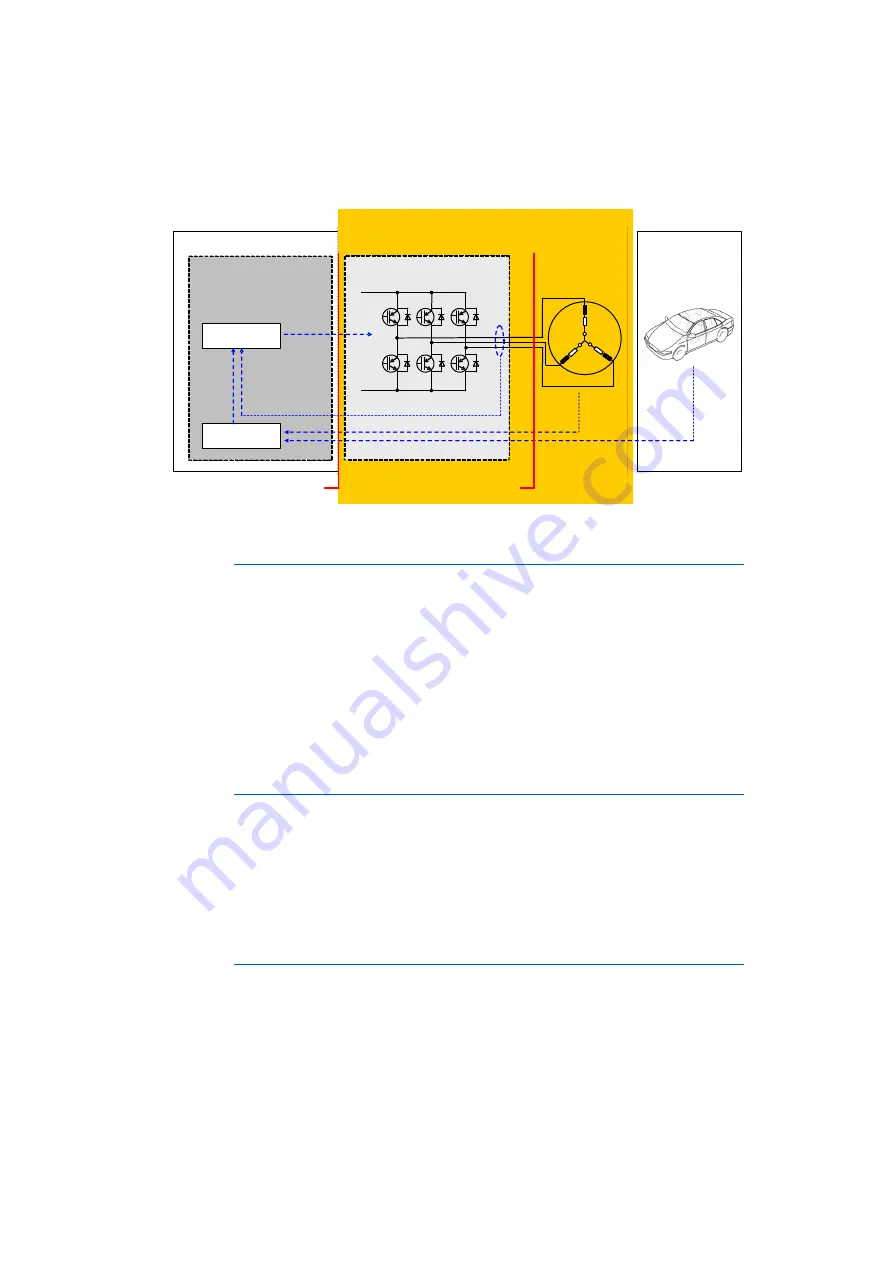
Fig. 1-1 below shows the components and interfaces of the complete "ECU - I/
O model (- DVE)" system.
Fig. 1-1
Components and interfaces of the ES5340.2
Parameterization of the Inverter
The inverter is configured using the typical variables, such as switching times,
polarity or resistances of the switches and diodes. In addition, for each switch,
the "open"/"closed" error states can be configured. Of course, what is known
as "free wheeling" (in which all 6 switches are open) can also be simulated.
In addition, for the entire inverter, the power loss of the ohmic components is
simulated – for the ohmic components, their value can also be calculated
depending on the temperature.
For the input wiring of the inverter, the internal resistance of the battery and the
capacity of the DC voltage link are taken into account – thus also allowing the
voltage in the DC voltage link to be simulated.
Parameterization of the PMSM
The PMSM is likewise configured via typical variables, such as the number of pole
pairs and cogging positions. Additional variables such as resistance, inductance,
the magnetic flow and the cogging torque can be changed during run time. This
ensures highly accurate simulation of the phase currents and electrical torque,
and all important variables can be changed in real time.
For the PMSM, the power loss of the ohmic components can also be simulated
and their temperature dependence can be calculated.
Parameterization the Connection to the Drive Train
For the mechanical connection to the drive train, the FPGA model also includes a
simulation of the spring-mass system. The system is configured with the typical
variables of coefficient of friction, moment of inertia for rotor and load, torsional
rigidity and damping. The load moment of the drive train can be preset and
changed during run-time.
ES5340
Sensor
Signals
Position
PMSM
Controller
ECU
IGBT
Control
Signals
Current
Controller
Application
Controller
Signal Level
Power Level
Vehicle
E-Motor
Power Stage
Current Signals
Summary of Contents for ES5340.2
Page 1: ...ES5340 2 Electric Drive Simulation Board User s Guide...
Page 6: ...ES5340 2 Electric Drive Simulation Board User s Guide 6 Contents ETAS...
Page 22: ...ES5340 2 Electric Drive Simulation Board User s Guide 22 Introduction ETAS...
Page 116: ...ES5340 2 Electric Drive Simulation Board User s Guide 116 ETAS Contact Addresses ETAS...
Page 118: ...ES5340 2 Electric Drive Simulation Board User s Guide 118 Figures ETAS...


