17
seCtIon 3
InstallatIon
IMproper grounDIng Can result In Death or InJurY.
ChassIs Must Be ConneCteD to an approVeD eleCtrICal
grounD. ensure sYsteM has a gooD earth grounD. see
grounDIng Your Manual.
Be sure grounD leaD Is not ConneCteD to anY prIMarY terMI-
nal.
eleCtrIC shoCK Can KIll! Dangerous Voltage anD Current!
anY tIMe WorKIng arounD a plasMa poWer sourCe WIth CoV-
ers reMoVeD:
Disconnect power source at line (wall) disconnect.
•
Have a qualified person check the output bus bars (positive and nega-
•
tive) with a voltmeter.
WarnIng
WarnIng
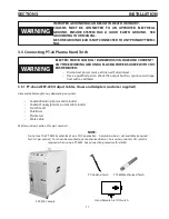
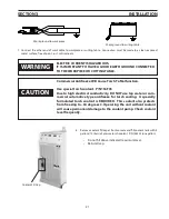
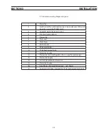
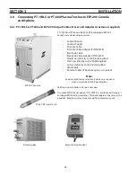
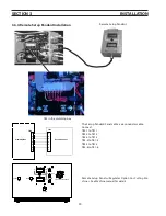
3.5 Connecting pt-26 plasma hand torch
3.5.1 pt-26 and esp-200 output Cables, hoses and adapters (customer supplied)
Hose and cable lengths vary depending on system.
Coolant Return (pilot arc cable inside)
•
Coolant Supply (plasma current cable inside)
•
Switch Lead
•
Shield Gas
•
Plasma Gas
•
Work Cable
•
SEE Description, Section 2 for part numbers.
note:
Do not use the PT-26M (mechanized) on a CNC application. A plumbing box is not available (required
for CNC gas control). Torch can be mounted on a mechanized tractor. An auxiliary pilot arc ON switch is
required when using a PT-26M. See connection procedure for details.
OFF
ON
ESP-200 Console
PT-26 Hand Torch
PT-26M Mechanized Torch
Hand Remote Arc ON Switch
Summary of Contents for ESP-200
Page 1: ...ESP 200 Plasmarc Cutting System Instruction Manual F15 462 C 02 2008 ...
Page 12: ...12 section 2 description ...
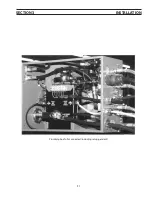
Page 31: ...31 section 3 installation Plumbing box fully connected including setup pendant ...
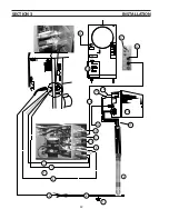
Page 32: ...32 CE 1 2 3 4 5 6 7 9 10 11 12 13 16 19 20 21 22 15 17 18 14 section 3 installation 8 ...
Page 84: ...84 section 7 replacement parts 1 2 3 4 5 6 7 8 9 10 11 12 13 7 6 Right Inside View ...
Page 88: ...88 section 7 replacement parts 6 1 4 5 6 R ef R ef 2 3 7 8 Back and Top Inside View ...
Page 92: ...92 section 7 replacement parts 1 2 3 4 5 6 7 8 7 10 Remote Setup Pendant P N 37145 ...
Page 100: ...100 notes ...


