26
seCtIon 3
InstallatIon
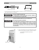
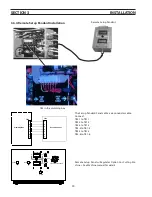
c. Attach coolant hoses (see Description, Section 2 for part numbers) to console and plumbing box.
note:
The supply and return coolant hoses between the ESP console and plumbing box have identical fittings.
It is possible to cross connect these hoses. Be very careful to connect console connection labeled “Pilot
Arc” with the P-box labeled “Cooling Water Out” and console connection labeled “Torch” with plumbing
box fitting labeled “Cooling Water IN”.
Plumbing Box Cooling
Water Connections
Console Cooling Water
Connections
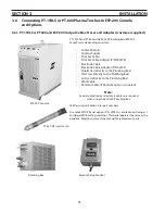
d. Connect pilot arc cable to one of 3 threaded holes on the outside of the adapter with supplied screw.
e. Attach electrode cable to one of 3 large threaded holes. As shown above.
note:
A large connection is necessary to safely carry the current in this circuit.
Pilot Arc Cable
Electrode Cable
Summary of Contents for ESP-200
Page 1: ...ESP 200 Plasmarc Cutting System Instruction Manual F15 462 C 02 2008 ...
Page 12: ...12 section 2 description ...
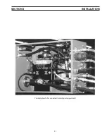
Page 31: ...31 section 3 installation Plumbing box fully connected including setup pendant ...
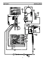
Page 32: ...32 CE 1 2 3 4 5 6 7 9 10 11 12 13 16 19 20 21 22 15 17 18 14 section 3 installation 8 ...
Page 84: ...84 section 7 replacement parts 1 2 3 4 5 6 7 8 9 10 11 12 13 7 6 Right Inside View ...
Page 88: ...88 section 7 replacement parts 6 1 4 5 6 R ef R ef 2 3 7 8 Back and Top Inside View ...
Page 92: ...92 section 7 replacement parts 1 2 3 4 5 6 7 8 7 10 Remote Setup Pendant P N 37145 ...
Page 100: ...100 notes ...


