36
seCtIon 4
operatIon
4.2 operating the esp-200 Console
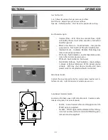
4.2.1 Console Controls
1
Pilot Arc High/Low Switch
2
Cutting Voltage and Cutting Current Meters
3
Output Current Control
4
Remote/Panel Selection Switch
5
Gas Test Switch
6
Fault Lights
7
Main Power Switch
7
6
1
2
3
4
5
Pilot Arc Switch
Used to select pilot arc current range. HIGH position is used for most cutting
applications. Electrode life is adversely affected when used in high position
when low is suitable. Starting may be difficult if set on low when high is re-
quired. Related to the initial torch standoff height.
Cutting Voltage and Current Meters
“A” meter indicates actual cutting current, 0-200 amperes
“V” meter indicates actual output voltage, 0-160 VDC
Output Current Control
Sets the cutting current when current settings are made from the power con-
sole front panel. (The Remote/Panel switch must be in the Panel position.)
Remote/Panel Switch
Panel position – Output current is set by the output current control on the
console front panel as described above.
Remote position – Output current is set by the CNC with an analog dc signal.
Summary of Contents for ESP-200
Page 1: ...ESP 200 Plasmarc Cutting System Instruction Manual F15 462 C 02 2008 ...
Page 12: ...12 section 2 description ...
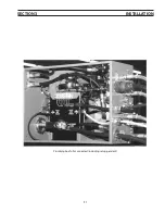
Page 31: ...31 section 3 installation Plumbing box fully connected including setup pendant ...
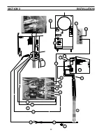
Page 32: ...32 CE 1 2 3 4 5 6 7 9 10 11 12 13 16 19 20 21 22 15 17 18 14 section 3 installation 8 ...
Page 84: ...84 section 7 replacement parts 1 2 3 4 5 6 7 8 9 10 11 12 13 7 6 Right Inside View ...
Page 88: ...88 section 7 replacement parts 6 1 4 5 6 R ef R ef 2 3 7 8 Back and Top Inside View ...
Page 92: ...92 section 7 replacement parts 1 2 3 4 5 6 7 8 7 10 Remote Setup Pendant P N 37145 ...
Page 100: ...100 notes ...


