


25
seCtIon 3
InstallatIon
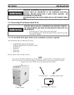
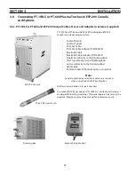
3.6.2 pt-19xls and pt-600 with esp-200 plumbing Boxtorch output Connection procedure
Electric Shock Can Kill!
Turn off primary input power at the wall disconnect box before making any connections
to the ESP-200.
WarnIng
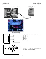
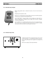
1. Thread 3 torch service lines (electrode cable, coolant supply, and coolant return) through large bushing at the middle
right side of front panel. Insert power arc cable through black grommet between the large bushing and work cable
plug. Proceed as follows:
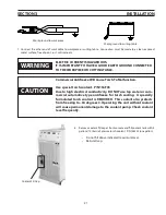
Thread service
lines through
bushing.
Pilot arc fitting
Pilot arc adapter
(P/N 999278)
Pilot arc cable here.
Coolant Supply/
Electrode Cable
connection
Coolant Supply
Hose/Electrode
Cable Adapter
a. Insert pilot arc adapter into left hand threaded Pilot Arc fitting and tighten with a wrench.
b. Thread cable adapter (P/N 36743) into coolant supply/electrode cable connection.
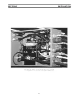
note:
Use of the ESP-200 plumbing box requires separation of coolant supply and electrode cable. The elec-
trode cable is inside the coolant supply hose for the PT-26 torch interface. (The PT-26 does not use a
plumbing box.)
Summary of Contents for ESP-200
Page 1: ...ESP 200 Plasmarc Cutting System Instruction Manual F15 462 C 02 2008 ...
Page 12: ...12 section 2 description ...
Page 31: ...31 section 3 installation Plumbing box fully connected including setup pendant ...
Page 32: ...32 CE 1 2 3 4 5 6 7 9 10 11 12 13 16 19 20 21 22 15 17 18 14 section 3 installation 8 ...
Page 84: ...84 section 7 replacement parts 1 2 3 4 5 6 7 8 9 10 11 12 13 7 6 Right Inside View ...
Page 88: ...88 section 7 replacement parts 6 1 4 5 6 R ef R ef 2 3 7 8 Back and Top Inside View ...
Page 92: ...92 section 7 replacement parts 1 2 3 4 5 6 7 8 7 10 Remote Setup Pendant P N 37145 ...
Page 100: ...100 notes ...


