


44
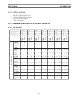
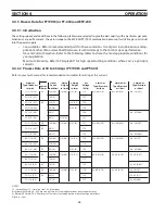
4.4.3 process Data for pt19xls (or pt-600) and esp-200
4.4.3.1 Introduction
seCtIon 4
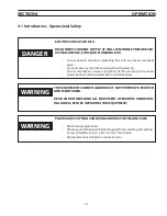
operatIon
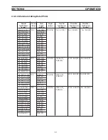
The cutting speeds and conditions in the following tables were selected to give the best quality with a particular gas com-
bination at a specific current. They are unique to the ESP-200/PT19XLS combination because of restrictive gas ports built
into the power supply
Consumables - Refer to recommended parts for these conditions. Use of parts in combinations and ap-
•
plications other than as described herein can result in damage to the torch or poor performance.
Gas and Current Selection- Refer to the following tables to chose the most appropriate conditions for
•
your application.
Maximum Economy- Refer to Paragraph D for high speed cutting conditions where cost is a principle
•
concern.
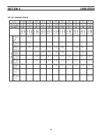
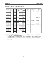
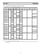
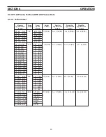
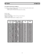
4.4.3.2 process Data at 50 to 65 amps (pt-19xls and pt-600)
Refer to your torch manual for recommended consumables for cutting at this current.
NOTES:
CS - Carbon Steel, SS - Stainless Steel, AL - Aluminum
Air Plasma/Air Shield, 50 - 65 Amp cuts on Stainless Steel and Aluminum have rough surfaces.
N
2
Plasma/N2 Shield, 50 - 65 Amp cuts of Stainless Steel and Aluminum have fair to good surfaces.
Pilot Arc -- Low
Current
(amps)
pierce
height
in. (mm)
Cutting
height
in.(mm)
arc
Voltage
(Volts)
CS - 1/16 (1.6)
50
220 (5.6)
1/4 (6.4) 5/32 (4)
115
Air - 40 (2.76)
Air - 60 (4.14)
Air - 30 (2.07)
CS - 1/8 (3.2)
120 (3)
112
CS - 1/8 (3.2)
65
120 (3)
1/8 (3.2)
110
CS - 3/16 (4.8)
95 (2.4)
5/32 (4)
118
CS - 1/4 (6.4)
80 (2)
120
Air - 65 (4.48)
CS - 3/8 (9.6)
40 (2)
5/16 (8)
122
SS - 1/16 (1.6)
50
180 (4.6)
1/4 (6.4) 5/32 (4)
111
Air - 40 (2.76)
Air - 60 (4.14)
Air - 30 (2.07)
SS - 1/8 (3.2)
65
80 (2)
119
SS - 1/4 (6.4)
60 (1.5)
118
Air - 65 (4.48)
AL - 1/16 (1.6)
50
180 (4.6)
1/4 (6.4) 1/8 (3.2)
116
Air - 40 (2.76)
Air - 60 (4.14)
Air - 45 (3.1)
AL - 1/8 (3.2)
110 (2.8)
115
AL - 1/4 (6.4)
65
65 (1.6)
5/32 (4)
128
Air - 65 (4.48)
AL - 1/16 (1.6)
50
180 (4.6)
1/4 (6.4) 1/8 (3.2)
118
N
2
- 40 (2.76)
N
2
- 60 (4.14)
N
2
- 30 (2.07)
AL - 1//8 (3.2)
120 (3)
117
AL - 1/4 (6.4)
65
70 (1.8)
125
N
2
- 65 (4.48)
SS - 1/16 (1.6)
50
180 (4.6)
1/4 (6.4) 5/32 (4)
119
N
2
- 40 (2.76)
N
2
- 60 (4.14)
N
2
- 30 (2.07)
SS - 1/8 (3.2)
65
80 (2)
125
N
2
- 45 (3.1)
SS - 1/4 (6.4)
55 (1.4)
127
N
2
- 65 (4.48)
travel
speed
ipm(M/m)
start gas
type/pressure
psi (bar)
plasma gas
type/pressure
psi (bar)
shield gas
type/pressure
psi (bar)
Material
type-thickness
in.(mm)
Summary of Contents for ESP-200
Page 1: ...ESP 200 Plasmarc Cutting System Instruction Manual F15 462 C 02 2008 ...
Page 12: ...12 section 2 description ...
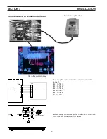
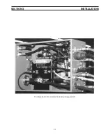
Page 31: ...31 section 3 installation Plumbing box fully connected including setup pendant ...
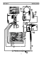
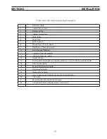
Page 32: ...32 CE 1 2 3 4 5 6 7 9 10 11 12 13 16 19 20 21 22 15 17 18 14 section 3 installation 8 ...
Page 84: ...84 section 7 replacement parts 1 2 3 4 5 6 7 8 9 10 11 12 13 7 6 Right Inside View ...
Page 88: ...88 section 7 replacement parts 6 1 4 5 6 R ef R ef 2 3 7 8 Back and Top Inside View ...
Page 92: ...92 section 7 replacement parts 1 2 3 4 5 6 7 8 7 10 Remote Setup Pendant P N 37145 ...
Page 100: ...100 notes ...


