


33
seCtIon 3
InstallatIon
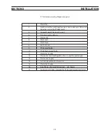
1
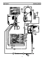
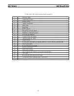
Electrode Cable
2
Coolant Return Hose
3
Pilot arc Cable
4
Coolant Supply Hose
5
Work Cable
6
Work Piece
7
Earth Ground
8
Plasma Torch (PT-600 shown)
9
Shield Gas In (from gas supply)
10
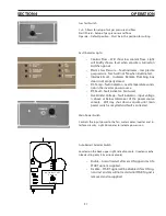
Setup Pendant (Remote)
11
Cut gas In (from gas supply)
12
Start Gas (from gas supply)
13
Height Control
14
Torch Bundle (Cooling Water: Supply and Return, Current: Pilot Arc and Electrode)
15
Flow Control (Front)
16
Remote Plumbing Box Cable
17
Shield Gas (to Torch)
18
Plasam Gas (to Torch)
19
Gas Connections on Console (not used in this application)
20
CNC Cable
21
Restart Switch (used on CE version only)
22
Current Input (from wall disconnect – not shown)
PT-600 (and 19XLS) Interconnecting Diagram Legend
Summary of Contents for ESP-200
Page 1: ...ESP 200 Plasmarc Cutting System Instruction Manual F15 462 C 02 2008 ...
Page 12: ...12 section 2 description ...
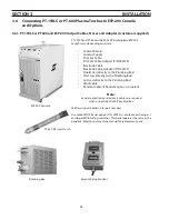
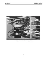
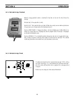
Page 31: ...31 section 3 installation Plumbing box fully connected including setup pendant ...
Page 32: ...32 CE 1 2 3 4 5 6 7 9 10 11 12 13 16 19 20 21 22 15 17 18 14 section 3 installation 8 ...
Page 84: ...84 section 7 replacement parts 1 2 3 4 5 6 7 8 9 10 11 12 13 7 6 Right Inside View ...
Page 88: ...88 section 7 replacement parts 6 1 4 5 6 R ef R ef 2 3 7 8 Back and Top Inside View ...
Page 92: ...92 section 7 replacement parts 1 2 3 4 5 6 7 8 7 10 Remote Setup Pendant P N 37145 ...
Page 100: ...100 notes ...


