


EDA 2530 Commissioning Procedure for Cable and Wireless Access
1/153 22-FGC 101 0239/2 Uen Rev J 2010-04-01
©
Ericsson AB 2010
Commercial in confidence
148 (200)
8.2
Alarm Checks
Check that the correct alarm is indicated on the LCT and on the rack, if applicable,
as follows:-
8.2.1
Common Part Alarm Check
a.
Using the optical connections listed in the resources, on the Common Part
unit housed in slot 1, connect together:-
The Tx of SFP Port 1 to the Rx of SFP Port 1, back haul interface (if fitted).
The Tx of SFP Port 2 to the Rx of SFP Port 2.
Note: If the SFP port is a SU57AF (1000Base-ZX) or SU57AJ
(1000Base-EX), then the Rx port MUST be fitted with an attenuator of
at least 5 dB. This ensures that the Rx port is not damaged by
overloading the port with an excessive signal level.
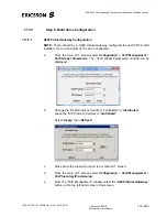
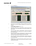
b. Select
the
Alarm Browser
→
Active Alarms
function on the LCT.
c. Check
the
Receive from all Cards
box. Click
Apply Settings
button and
check that there are no active alarms relevant to the electronic units.
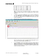
d.
On the Common Part unit in slot 1, disconnect the loop on SFP Port 1 and
check for the occurrence of the
critical
alarm.
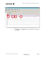
e.
On the Common Part unit in slot 1, disconnect the loop on SFP Port 2 and
check for the occurrence of the
critical
alarm.
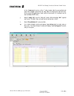
f.
Reconnect the loops on both SFP Ports on the Common Part unit in slot 1,
check the alarms clear for SFP Port 1 and SFP Port 2.
g.
Check on the unit front that all equipped units, have their Green and Yellow
LED’s lit and the Red LED extinguished.
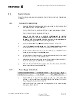
8.2.2
Power Supply Alarm Check
SUBRACK DESCRIPTION
SUBRACK CODE
Power Supply – Right
S20 Flexible Connections
133-1555/03
151-2975/53 (Slot 22)
a.
Switch OFF the 1
st
and 2
nd
Circuit Breakers at the top of the EDA 2530
cabinet. This will disconnect the power supply from Socket Vb1 on the
Power Supply Connection Unit in slot 22.
Check the Green Vb1 PWR LED is extinguished on the Power Supply
Connection Unit in slot 22.