EDA 2530 Commissioning Procedure for Cable and Wireless Access
1/153 22-FGC 101 0239/2 Uen Rev J 2010-04-01
©
Ericsson AB 2010
Commercial in confidence
138 (200)
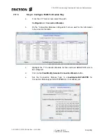
Change the 1
st
entry in this column to the correct IP address, select the 1
st
entry, then left-click the 1
st
entry & drag down to the bottom of the column
to highlight all entries. Right click & select “
Replicate cell
”, all entries in
the “
Ne Name”
column will now be set to the required OOB IP Address.
Note:
In this example Slot 3 is used for the descriptions.
m.
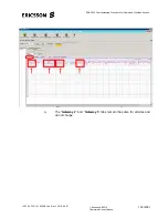
The Signalling Gateway “
Domain Name
” field data must be entered, which
has a unique Identifier number which relates to a specific POTS line card.
Each POTS card “Domain Name” is specified in the “CWA Voice Card
Deployment” spreadsheet.
Note:
The “Domain Name” is defined as
nnnn-DLEID-COLO#SLOT#
Nnnn = Four digit Domain Name Instance number (e.g. 0016 is New Cross)
DLEID = Site DLE identifier (e.g. CLNEW)
COLO# = Node Co-location identifier (e.g. 0203)
SLOT# = Slot the POTS card is installed in for this gateway
n.
The Signalling Gateway “
IP Address
” field must be entered. This address
is unique for each POTS line card for the slot position and is also site
specific. This is specified in the “CWA Voice Card Deployment”
spreadsheet.
o. The
“
Default GW IP Addr
” field must be filled in with the Default GW
address for the specific POTS card.
Explanation:
The Def GW IP Address is determined from the POTS card
IP Address, if the POTS card IP Addr = a . b . c . d
So the Def GW IP Addr becomes =
a . b . c+1 . 254
In this example the Def GW IP Address for POTS card in slot 3 has been
used:-
POTS
Slot No.
Identifier
POTS Card IP
Addr
POTS Card
Def GW Addr
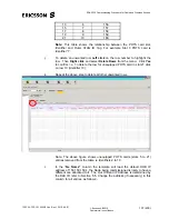
3 1 10.67.130.102
10.67.131.254
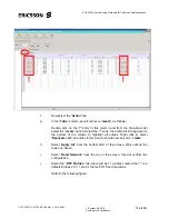
Refer to the following figure.
p. The
“
Outer VLAN Id Tag (-1…4094)
” column will be filled in by the
“
Generic H248 VGW Configuration Slots 3 to 21.hvgw”
file when it is
loaded in step f.
For example:- The slot 3 entry in this column will be 151 and will be
standard for all sites.
For Information Only:
This is the VLAN the POTS card is to be built in
(e.g.Slot3 = 151, Slot5 = 152, Slot7 = 153…, Slot19 = 159, Slot21 = 160).

