background image

The Face-up Output Tray

Then set the OUTPUT option in SelecType Level 

for face-up

paper delivery. See Chapter 3 for instructions on using Selectype.

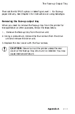
Removing the face-up output tray

When you need to remove the face-up tray from the printer for

transportation or other purposes, follow the steps below.

1. 

Remove the face-up tray from the drive unit.

2. Using a screwdriver, remove the four screws from the drive

unit and remove the drive unit.

3. Replace the rear cover with the four screws.

CAUTION: 

Never turn on the printer unless the rear

cover or the face-up tray drive unit is installed. You may

cause mechanical failure.

Appendix A

A-19

Summary of Contents for EPL-7500

Page 1: ......

Page 2: ...uipment It is the responsibility of the user to obtain and use a shielded equipment interface cable with this device If this equipment has more than one interface connector do not leave cables connected to unused interfaces Seiko Epson Corporation shall not be liable against any damages or problems arising from the use of any options or any consumable products other than those designated as Origin...

Page 3: ......

Page 4: ...vant Garde ITC Bookman ITC Zapf Chancery ITC Zapf Dingbats and Stone are registered trademarks of International Typeface Corporation IBM and IBM PC are trademarks of International Business Machines Corporation LaserJet LaserJet LaserJet 500 LaserJet series II and LaserJet series IIP are trademarks of Hewlett Packard Company Apple AppleTalk and LaserWriter are registered trademarks of Apple Compute...

Page 5: ...enings should never be blocked by placing the product on a bed sofa rug or other similar surface This product should never be placed near or over a radiator or heat register This product should not be placed in a built in installation unless proper ventilation is provided 7 This product should be operated from the type of power source indicated on the marking label If you are not sure of the type ...

Page 6: ... Remove may expose you to dangerous voltage points or other risks Refer all servicing in those compartments to service personnel 13 Unplug this product from the wall outlet and refer servicing to qualified service personnel under the following conditions A When the power cord or plug is damaged or frayed B If liquid has been spilled into the product C If the product has been exposed to rain or wat...

Page 7: ...NG Use of controls adjustments or performance of procedures other than those specified in this guide may result in hazardous radiation exposure The label shown below indicates that the printer is a Class 1 laser product as defined in BS4803 and IEC 825 specifications Internal Laser Radiation Maximum Radiation Power 2 42 X l0 4 W Wavelength 780 nm This is a Class IIIb Laser Diode Assembly that has ...

Page 8: ...is amount is not large enough to affect human beings adversely However it is best to make sure the room where you a using the printer has adequate circulation especially if you are printing a high volume of materials or using the printer continuously over a long period of time vi ...

Page 9: ...nel 2 2 Testing the Printer 2 6 Connecting to Your Computer 2 16 Chapter 3 SelecType 3 1 SelecType Overview 3 2 Using SelecType 3 4 SelecType Options 3 9 Chapter 4 Paper Handling 4 1 Choosing Paper 4 2 Choosing a Paper Size 4 5 Choosing Printing Methods 4 6 Loading Paper in the Cassette 4 9 Loading Paper Manually 4 13 Chapter 5 Application Software 5 1 Using Your Printer with Application Software ...

Page 10: ... Problems with Graphics 7 22 SelecType Problems 7 23 Paper Handling 7 24 Decline in Print Quality 7 28 Options 7 34 Chapter 8 Technical Specifications 8 1 Printer Specifications 8 2 Interface Specifications 8 10 Initialization 8 17 Option Specifications 8 24 Appendix A Options A 1 The Lower Paper Cassette A 2 The Face up Output Tray A 14 The Memory Expansion Board A 20 Appendix B Character Samples...

Page 11: ... technology used in office copiers to give you high quality printing that is both fast and quiet Features In addition to the superior printing and easy operation you d expect from an Epson printer these features make the EPL 7500 your best choice for today s desktop publishing The Adobe PostScript Language This powerful printer language easily rotates scales clips and orients any graphic object on...

Page 12: ...otoconductive developing and toner elements in a single disposable cartridge Replace it in minutes for simple printer maintenance Two paper delivery methods Choose standard face down delivery for your everyday printing needs or add the optional face up tray for printing on special media like labels or very heavy paper A SelecType control panel for easy configuration control Customize your printer ...

Page 13: ...l cassette expands your standard paper cassette s 250 sheet capacity to 500 sheets The face up output tray C812071 or C812072 The face up output tray delivers paper face up for immediate viewing of your printed output Also use the face up output tray for printing that requires a straight through paper path such as labels overhead transparencies and heavy paper Introduction 3 ...

Page 14: ...MB of RAM to your printer With this board you can increase your printer s memory to a powerful 6 MB of RAM for rapid processing of the most complex graphics Accessories and supplies To locate or purchase accessories or supplies contact your nearest Epson dealer or call 1 800 873 7766 4 Introduction ...

Page 15: ...hen the power is on Do not touch the areas marked by a high voltage label l Be careful not to touch the fuser which is marked by a CAUTION HOT SURFACE label If the printer has been in operation the fuser can be very hot l Protect the light sensitive drum from exposure to light You should avoid exposing the imaging cartridge to room light for any longer than necessary Do not open the drum s protect...

Page 16: ... scratch the surface of the drum Also avoid touching the drum since oils from your skin can permanently damage its surface and may affect print quality l Avoid pressing on the top of the toner cartridge Pressing directly on the cartridge may cause toner to spill into the printer If there is a spill see Chapter 6 for cleaning instructions l Never try to force the printer s components into place Alt...

Page 17: ...n on using the printer with software while Chapter 6 gives you information on maintaining your printer If the EPL 7500 does not operate properly or the printed results are not what you expect see Chapter 7 for troubleshooting tips Other chapters and appendixes contain information on technical specifications printer options and printer modes The appendixes contain available character samples The ma...

Page 18: ...provides product information and support to its dealers and Customer Care Centers Therefore we ask you contact the business where you purchased your Epson product to request assistance If the people there do not have the answer to your question they can obtain it through our dealer support program Epson is confident that this policy will provide you with the assistance you need Call the Epson Cons...

Page 19: ...pening the printer cover 1 4 Unpacking the Printer l 6 Carrying the printer l 10 Assembling the Printer l 11 Installing the cleaning pad l 11 Installing the imaging cartridge l 13 Installing the paper cassette l 19 Attaching the power cord l 21 Setting Up the Printer l l ...

Page 20: ...flat stable surface Place the printer close enough to the computer or workstation for its cable to reach Use a grounded outlet one that has three holes to match the power plug on the printer Do not use an adapter plug Leave adequate room around the printer to allow easy printer operation and maintenance The diagram below shows the amount of space recommended for your printer l 2 Setting Up the Pri...

Page 21: ...ure there is 330 mm 13 inches of flat unobstructed space to the left of the printer to accommodate the tray To give you enough room to open the printer cover allow 430 mm 17 inches from the bottom of the printer to any shelf or surface directly above the printer as shown below Setting Up the Printer l 3 ...

Page 22: ...ift the latch to open the printer cover it stops automatically in the lower position at an angle of about 45 degrees This position protects the imaging cartridge from overexposure to light When you lift the cover as far as it will go it stops at the upper position about 70 degrees The instructions in this manual tell you which position to use for each task Avoid using electrical outlets that are c...

Page 23: ...Finding a Place for the Printer Lower position 45 Upper position 70 Setting Up the Printer 1 5 ...

Page 24: ... unpack the large main carton At the top of this carton is the accessory pack containing several printer components Under this is the printer itself which is protected by white packing material 1 Remove the accessory pack and make sure you have the accessories shown below 1 6 Setting Up the Printer ...

Page 25: ... may need someone to help you lift it 3 Remove the plastic bag protecting the printer Then remove the plastic bag from the paper cassette Note Make sure that you save all packing materials You must repack the printer in these materials whenever you transport it See Chapter 6 for details on transporting your printer Setting Up the Printer 1 7 ...

Page 26: ...Unpacking the Printer 4 Remove the tape from the printer and the paper cassette 5 Use the wrench to unscrew the two screws on the front of the printer as shown below 1 8 Setting Up the Printer ...

Page 27: ...it will go as shown below Remove the protective plate 7 To close the printer gently press down on the top of the case until the latch clicks shut 8 Finally check to see that neither the printer nor any of the accessories has been damaged during transportation Setting Up the Printer 1 9 ...

Page 28: ...printer to the location you selected for it carry it by grasping the recesses on each side of the printer as shown below Note The printer weighs about 18 kg 40 lb and should be carried with care You may need someone to help you lift it 1 10 Setting Up the Printer ...

Page 29: ...its operating location before you install the parts Installing the cleaning pad The first component that you need to install is the cleaning pad It is packaged inside the imaging cartridge box The felt cleaning pad constantly cleans the surface of the fusing roller which fixes toner onto the paper Setting Up the Printer 1 11 ...

Page 30: ... and take out the cleaning pad Leave the imaging cartridge cotton swab and packing materials inside the box for now you will use them later 2 Lift up the front latch and open the printer cover to the upper position as shown below 1 12 Setting Up the Printer ...

Page 31: ... in the correct position match the triangle on the cleaning pad with the triangle on the fuser as shown below Installing the imaging cartridge The imaging cartridge forms the image and transfers it onto the paper See Chapter 6 for information on imaging cartridge life CAUTION The drum is light sensitive Do not expose it to light any longer than necessary and do not expose it to light brighter than...

Page 32: ...you handle the imaging cartridge Do not turn the cartridge upside down l Do not open the drum s protective cover Do not scratch or mar the surface of the drum Also do not touch the drum since oils from your skin can permanently mar its surface and may affect print quality 1 14 Setting Up the Printer ...

Page 33: ...dge It cannot be refilled l Do not use a cartridge for at least one hour after moving it from a cool to a warm environment Storing the imaging cartridge Follow these storage precautions to get the best print quality from your imaging cartridge l Do not store in direct sunlight l Do not store in dusty places l Do not store where salty air or corrosive gasses such as ammonia are present l Do not sto...

Page 34: ...imaging cartridge from its aluminum packing bag CAUTION Do not open the drum s protective cover It protects the drum from light and contact 2 Hold the imaging cartridge as shown below and shake the cartridge from side to side a few times to distribute the toner 1 16 Setting Up the Printer ...

Page 35: ...ng the Printer 3 Pull the yellow tab firmly as shown below to remove the clear seal completely 4 After you remove the seal gently shake the imaging cartridge again four or five times Setting Up the Printer 1 17 ...

Page 36: ... in the lower position 6 Hold the imaging cartridge as shown below Carefully place the plastic runners on either side of the cartridge into the green grooves inside the printer and slide the cartridge forward as far as it will go 1 18 Setting Up the Printer ...

Page 37: ...p of the case until the latch clicks shut CAUTION Never transport the printer with the imaging cartridge installed See Chapter 6 for details on moving or transporting the printer Installing the paper cassette Before you install the paper cassette make sure you have removed the tape from the cassette Setting Up the Printer 1 19 ...

Page 38: ...er side of the paper cassette with the metal pins inside the printer then lower the paper cassette into place as shown below Note Make sure the notches fit securely onto the pins on the printer If the paper cassette is not installed properly an OUT OF PAPER error may appear on the display 1 20 Setting Up the Printer ...

Page 39: ... switch at the rear of the printer is turned off It is off when the O on the switch is pressed toward the printer as shown below WARNING If the rated voltage of the printer and your outlet voltage do not match contact your dealer for assistance Do not plug in the power cable Setting Up the Printer 1 21 ...

Page 40: ...sembling the Printer 2 Insert the power cord into the socket at the back of the printer as shown below Then plug the other end of the power cord into a properly grounded outlet 1 22 Setting Up the Printer ...

Page 41: ...er for a start page 2 6 Turning on the printer 2 10 Adjusting the print density 2 13 Connecting the Printer to Your Computer 2 16 IBM and compatible computer users 2 16 Macintosh users 2 16 Connecting the parallel interface cable 2 18 Other interface selections 2 20 Connecting the serial interface cable 2 22 Testing and Connecting Your Printer 2 1 ...

Page 42: ... of information displayed and an example of each are given below Status messages such as WARMING UP indicate the printer s current status Maintenance and error messages such as COVER OPEN inform you of maintenance procedures that must be performed or of error conditions SelecType options such as MODE allow you to control printer mode font selection paper handling and many other printer functions F...

Page 43: ... can receive and print data When the printer is off line this light is off CONTINUE This light is on when the printer is in HP emulation mode and there is information on the page It has no meaning in Post script mode CH S CH P One of these lights goes on when data is received by the indicated channel and is stored in the printer without being printed out The CH S light is for AppleTalk or a serial...

Page 44: ...here is anything on the current page pressing this button causes the printer to print the page If there is nothing on the current page this button is ignored This button operates only if the ON LINE light is on and WAITING appears on the display This button is inactive in other modes ON LINE Switches the printer between on line READY and off line status This switch is disabled when you are in Sele...

Page 45: ... is flushed from the printer s memory If you press any other buttons the printer returns to its previous status without printing data Select Type Enters or exits SelecType mode Press once to enter Level 1 press twice to enter Level 2 For a complete description of the two SelecType levels and their functions see Chapter 3 Testing and Connecting Your Printer 2 5 ...

Page 46: ...gs and lets you know the printer is working properly and ready to print You can also print test prints with the TEST PRINT option in SelecType Level 2 See Chapter 3 Before you turn on the printer make sure you have removed all packing material from the printer as described in Chapter 1 installed all the components and loaded paper as described in the following section You do not need to connect th...

Page 47: ...Testing the Printer 1 Push the paper set lever forward to the manual position 2 Slide the paper guides all the way open as shown below Testing and Connecting Your Printer 2 7 ...

Page 48: ...the edges of the paper on a flat surface to even up the stack 4 Insert the stack of paper into the paper cassette making sure that the top of the stack does not exceed the maximum height mark inside the cassette as shown below Gently push the paper in as far as it will go 2 8 Testing and Connecting Your Printer ...

Page 49: ...Testing the Printer 5 Slide the paper guides together until they both rest lightly against the paper 6 Pull the paper set lever back to the automatic position Testing and Connecting Your Printer 2 9 ...

Page 50: ... paper in the paper cassette Now you re ready to turn on the printer and print a start page Turning on the printer Make sure the printer is plugged in and the imaging cartridge is installed then turn on the power by pressing the vertical bar 1 on the power switch located at the back of the printer All of the lights on the control panel light briefly at power on The following messages appear on the...

Page 51: ... the printer to complete its power on routine Then the printer automatically prints the start page After the page has printed the printer is on line and the display shows READY If the display remains blank see Chapter 7 for troubleshooting information The start page contains information about several current parameters of your printer A typical start page printout is shown on the next page Testing...

Page 52: ...Testing the Printer 2 12 Testing and Connecting Your Printer ...

Page 53: ...oting information Adjusting print density You can control the overall density of the printed image with the print density control knob If your test print is too light or too dark adjust the print density as follows 1 Lift the latch to open the printer cover to the lower position 2 Locate the yellow density control knob inside the front right corner of the printer as shown below Testing and Connect...

Page 54: ...f you select darker print you may need to replace the imaging cartridge more often 4 For lighter print turn the knob counterclockwise as shown Note If you want to return the print density setting to the factory setting center position align the vertical line on the knob with the dot on the scale 2 14 Testing and Connecting Your Printer ...

Page 55: ... Printer 5 Close the printer cover 6 Print a start page again to check the new print density setting To do this turn the printer off wait five seconds and turn it on again Testing and Connecting Your Printer 2 15 ...

Page 56: ...n this chapter Macintosh users Follow the simple 10 step procedure below to select the EPL 7500 s AppleTalk interface and then connect your Mac to the printer with a properly shielded AppleTalk cable CAUTION Do not connect the cable before you have selected the AppleTalk interface on the EPL 7500 To select the AppleTalk interface follow these steps 1 Turn on the printer and wait until it prints th...

Page 57: ...ss until SAVE LEVEL 2 appears on the display 9 Press once 10 Turn the printer off CAUTION If you connect an AppleTalk cable never operate the printer with the SelecType INTERFACE option set to any other interface Failure to use the APPLETALK setting may leave your printer inoperable or bring down your entire system Now connect the AppleTalk interface cable 1 Turn off both the printer and the Macin...

Page 58: ...erface cable The EPL 7500 is set up at the factory for parallel communication If your computer has a parallel interface and you have a suitable shielded cable you can connect to most computers immediately Follow these steps to connect the parallel interface cable 1 Turn off both your printer and computer Then unplug the power cord from the electrical outlet 2 1 8 Testing and Connecting Your Printe...

Page 59: ...puter 2 Plug the cable securely into the CH P parallel interface connector of the printer as shown below 3 Squeeze the wire clips together until they lock in place on either side of the connector Testing and Connecting Your Printer 2 19 ...

Page 60: ...r computer Some parallel cables have grounding wires at the computer end as well If so connect this wire to the ground screw on the computer Other interface selections The EPL 7500 has four built in interfaces two of which are discussed earlier in this chapter l Centronics compatible parallel l RS 232 serial l RS 422 serial l AppleTalk 2 20 Testing and Connecting Your Printer ...

Page 61: ...n your computer PC users can choose the parallel or serial interfaces Apple Macintosh users must use the AppleTalk interface The EPL 7500 is set up for parallel communication Parallel communication is best for PC users because it is faster than serial communication If you are an experienced PostScript user and want to use the interactive mode or if your computer does not have a parallel port choos...

Page 62: ...ct one for your computer and the EPL 7500 Be sure to change the SelecType Level 2 INTERFACE setting to the serial mode you want to use before you connect the interface Save the new setting with the SAVE LEVEL 2 option See Chapter 3 for instructions on changing SelecType settings Connecting the RS 232 serial interface cable Follow these steps to connect the RS 232 serial interface cable 1 Turn off ...

Page 63: ...the screws of the connector if required 4 If your cable has a grounding wire connect it to the printer s ground connector 5 Plug the other end of the cable into your computer Fasten the connector screws to the interface if required Testing and Connecting Your Printer 2 23 ...

Page 64: ...s of the cable into your computer Fasten the connector screws to the interface if required This completes the connection of the RS 422 serial interface cable Before you can use the printer make sure you have set the printer for RS 422 serial communication You may need to change some interface settings with the SelecType INTERFACE option in Level 2 Be sure to save the new setting with the SAVE LEVE...

Page 65: ...rview 3 2 SelecType Level 1 functions 3 3 SelecType Level 2 functions 3 3 Using SelecType 3 4 Buttons lights and the display 3 4 Steps to using SelecType 3 5 SelecType Options 3 9 Level 1 options 3 9 Level 2 options 3 16 SelecType 3 1 ...

Page 66: ...s as shown below A brief description of each main menu option follows See SelecType Options later in this chapter for detailed descriptions of main menu and submenu options For complete instructions on using SelecType see Steps to using SelecType later in this chapter Level 1 SOFTWARE INPUT OUTPUT MISCELLANEOUS Level 2 INTERFACE MISCELLANEOUS Note See the Quick Reference Card at the back of this m...

Page 67: ...s Level 1 settings sets paper jam recovery and displays the amount of memory available in each software mode SelecType Level 2 functions INTERFACE Sets up the interface configuration MISCELLANEOUS Returns all Level 2 settings to their factory settings turns the beeper on or off prints a test page saves Level 2 settings turns the standby mode on or off displays the number of pages the printer has p...

Page 68: ...tions like the SOFTWARE option lead you to a list of further choices some options like the PAGES option display information and some options like the TEST PRINT option cause the printer to perform an action If an option leads to a list of choices or to another option you can press to see further choices Some options require no action at all they simply display information Enters and exits SelecTyp...

Page 69: ...time by pressing the buttons Note If you press an arrow that is invalid the printer beeps three times and does not change the display Steps to using SelecType There are five steps to useing SelecType 1 Enter SelecType mode 2 Move to the option you want to select 3 Select the option 4 Save the new setting if necessary 5 Exit SelecType mode You ll see how to complete each step on the following pages...

Page 70: ...e desired option When you enter SelecType Level 1 or Level 2 one of the main menu options appears on the display To look at the other options at this level you can use the and buttons 1 Press until the OUTPUT option appears on the display as shown below 2 Press to enter the next level of the OUTPUT option This option has two choices The currently selected OUTPUT option appears on the display as sh...

Page 71: ...hows that FACE UP is selected It remains selected only until you change it or turn off the printer unless you save the Level 1 settings as described in the next section Note If you press to select an option that is already selected IS SELECTED appears briefly on the display Now FACE UP is selected but it does not affect the operation of your printer unless you have installed the face up output tra...

Page 72: ...LLANEOUS appears on the display Press to enter the MISCELLANEOUS submenu One of the five options in the MISCELLANEOUS submenu appears on the display Press o r to move to the SAVE LEVEL 1 option as shown below Press m to execute the save The printer beeps when the save is complete Exit SelecType Press ON LINE to exit SelecType mode Next go through the entire exercise again but select FACE DOWN Then...

Page 73: ... listed below appears on the display SOFTWARE INPUT OUTPUT MISCELLANEOUS Each of these options is described below An asterisk indicates the factory default setting for each option POSTSCRIPT HP LASERJET II PS BINARY This option selects one of three operating modes that the printer can use The PostScript mode offers the widest range of features PS Binary mode is a binary protocol and host switching...

Page 74: ...al lower paper cassette or the manual feed slot If you choose STANDARD the printer loads paper from the standard paper cassette If you choose OPTION the printer loads paper from the optional lower paper cassette If you want to feed paper manually choose MANUAL FEED If the optional lower paper cassette is not installed or if the paper tray is not correctly installed in the lower paper cassette NO P...

Page 75: ...for different countries This option sets the printable area for the chosen paper size not the actual paper size Even if the selected paper size doesn t match the paper you load into the standard paper cassette the printer loads a page from the location specified with the TRAY option and prints within the printable area specified by the PAPERSIZE STD TRAY setting CAUTION Be absolutely sure that you...

Page 76: ...The factory default setting is different for different countries This option sets the printable area for the chosen paper size not the actual paper size Even if the selected paper size doesn t match the paper you load into paper cassette the printer loads a page from the location specified with the TRAY option and prints within the printable area specified by the PAPERSIZE OPT TRAY setting CAUTION...

Page 77: ... more information on installing the optional face up tray If you select FACE UP without installing the face up tray and moving the paper path lever the setting has no effect Note Some application software programs distinguish between face down and face up paper delivery For those programs see your software documentation to set the correct paper delivery This option includes the 5 submenus shown be...

Page 78: ... 1 settings so that they are in effect each time you turn the printer on Press to exit this submenu without saving settings PARTIAL COMPLETE When this option for paper jam recovery is set to PARTIAL a jammed page is not automatically reprinted when you clear the jam In most cases leave the RECOVERY option set to PARTIAL because complex pages may print faster When this option is set to COMPLETE and...

Page 79: ...ys the amount of memory available for the HP emulation mode LJ ALLOCATION specifies the proportion of memory for HP emulation mode The proportion of memory can be set from NONE 0 to 100 by 10 increments Press or to change the setting The setting becomes effective after you save the setting with SAVE LEVEL 1 option and turn the printer off then back on Leave the setting at 0 unless you need to use ...

Page 80: ...tting PARALLEL SERIAL RS232 SERIAL RS422 APPLETALK This option selects the printer interface The printer has four interfaces PARALLEL SERIAL RS232 and SERIAL RS422 have submenus to set other configuration settings The APPLETALK option has no submenus CAUTION Whenever you change the INTERFACE setting make sure you save the new setting with the SelecType SAVE LEVEL 2 option and turn the printer off ...

Page 81: ... settings are 5 0 and 5 microseconds For most applications leave this option set to 0 microseconds The SERIAL RS232 and SERIAL RS422 options have these submenus BAUD RATE PARITY FLOW CONTROL RS232 only STOP BITS A brief description of each serial interface option follows 300 BAUD 600 BAUD 1200 BAUD 2400 BAUD 4800 BAUD 9600 BAUD 19200 BAUD 38400 BAUD 57600 BAUD RS422 only SelecType 3 17 ...

Page 82: ...our computer manual and software documentation for the proper setting XON XOFF DTR XON XOFF DTR This option is available only with SERIAL RS232 You can select serial communication from two options the XON XOFF communication protocols or the DTR Data Terminal Ready signal levels When the vacant area for data in the input buffer drops to 128 bytes the printer outputs an XOFF code indicating that it ...

Page 83: ...r 7 DATA BITS 8 DATA BITS of a You can select a word length for serial communications from two options B bit word length or 7 bit word length See your computer manual and software documentation for the proper setting This option includes the eight submenus shown below BEEPER STARTPAGE TEST PRINT SAVE LEVEL 2 PAGES XXX FACTORY RESET ERROR HANDLER STANDBY SelecType 3 19 ...

Page 84: ...nter on The start page contains simple text and graphics and lets you know the EPL 7500 is ready When this option is off the printer does not print a test print when you turn on the printer Even if the STARTPAGE option is set to off you can print a test print using the TEST PRINT option described below Use this option to print a test print to check whether your printer is working correctly Move to...

Page 85: ...on LETER A4 FACTORY RESET returns all Level 1 and 2 settings to their factory default settings When you select this option the display shows LETTER or A4 Choose the one that you wish to be the default setting for PAPERSIZE STD TRAY and PAPERSIZE OPT TRAY in SelecType Level 1 Then press to execute the reset or press twice to return to the main menu without resetting the printer SelecType 3 21 ...

Page 86: ...rface STANDBY DISALLOWED STANDBY ALLOWED The standby mode is designed to save power by reducing the power to the fixing heater whenever no panel buttons are pushed or data sent to the printer for 30 minutes In this mode the printer begins warming up as soon as you press any button or send any data becoming ready to print within 70 seconds The default is DISALLOWED which keeps the printer warmed up...

Page 87: ...er Handling Choosing Paper 4 2 Choosing a Paper Size 4 5 Choosing Printing Methods 4 6 Paper delivery method 4 6 Paper feed method 4 7 Loading Paper in the Cassette 4 9 Loading Paper Manually 4 13 Paper Handling 4 1 ...

Page 88: ...s fall into indentations on the paper The smoother the paper you use the better your printing looks You should use especially smooth paper for printing originals that will be used to make reproductions Because reproduction introduces its own raggedness to the edges of the letters you want to start with the best original possible For best results store your paper supply in its original wrapper Prin...

Page 89: ...s or dyes that may smear or come off when subjected to the high temperatures of the fuser Try a few sheets before you print on letterhead or other special paper Special paper You can use colored paper as long as it meets the weight limits given above for standard office paper Do not however use coated paper paper to which a colored coating has been added Labels Use only labels designed for laser p...

Page 90: ... density knob counterclockwise Always return the print density knob to the center position when you go back to printing on ordinary paper Also for better printing of envelopes use the optional face up output tray Other materials You can use overhead projector transparencies and adhesive drafting film if they are made for use with plain paper copiers or laser printers When printing these materials ...

Page 91: ...u Not all the sizes in this table are marked on the paper cassette just the more commonly used paper sizes Paper letter 8 5 X 11 inches A4 210 X 297 mm A5 148 X 210 mm B5 182 X 257 mm halfletter 5 5 X 8 5 inches legal 8 5 X 14 inches glt Government letter 8 X 10 5 inches glg Government legal 8 5 X 13 inches executive 7 25 X 10 5 inches F4 210 X 330 mm You will probably use one paper size most of t...

Page 92: ...al face up tray The advantage of printing face down is that when the printed stack is turned over the first page of the document is on top and the last page on bottom The printer is factory set for face down delivery The optional face up tray gives you immediate viewing of your printed output Also this method of delivery is recommended for printing on media such as labels envelopes and overhead tr...

Page 93: ...elivery when the face up output tray is installed move the paper path lever to FACE DOWN and set the OUTPUT option to face down Paper feed method The printer feeds most types of media automatically from the paper cassette however some media require hand feeding for greater control The following table lists recommended settings for different print media If you want to try other settings be sure to ...

Page 94: ...lopes Transparencies Labels Feed Delivery Auto or manual Face up or face down Manual or auto Face up Manual or auto Face up or face down Manual Face up or face down Manual Face up Note To print on letterhead paper load the paper face up with the top of the paper entering the printer first 4 8 Paper Handling ...

Page 95: ...paper cassette holds up to 250 sheets of paper To load paper in the cassette follow these steps 1 Push the paper set lever forward to the manual position as shown below 2 Slide the paper guides all the way apart as shown below Paper Handling 4 9 ...

Page 96: ...f the paper on a flat surface to even up the stack as shown 4 Insert the stack of paper into the paper cassette making sure that the top of the stack is below the maximum height mark inside the paper cassette Push the paper in gently as far as it will go 4 10 Paper Handling ...

Page 97: ...ssette Note To print on long paper such as legal size paper 8 l 2 X 14 inches open the paper support as shown below 5 Slide the paper guides together until they both rest lightly against the stack of paper Paper Handling 4 11 ...

Page 98: ...he paper set lever is forward while the printer is on the control panel displays the OUT OF PAPER message even if there is paper in the cassette 7 If you have changed the paper size use SelecType to choose the new paper size as described in Chapter 3 8 Press ON LINE to set the printer on line Note When you reload paper make sure the output roller stops rotating before you insert a new stack of pap...

Page 99: ... is already loaded in the cassette You can hand feed paper ranging in size from 92 X 160 mm 3 62 X 6 3 inches to 216 X 356 mm 8 5 X 14 inches It is easy to hand feed paper with this printer just follow the steps below 1 Set the SelecType Level 1 TRAY option to MANUAL FEED See Chapter 3 to use SelecType 2 If necessary use SelecType to choose the new paper size as described in Chapter 3 3 If the pri...

Page 100: ...eed paper guides to match the size of paper you are using as shown below 6 Insert a sheet of paper into the manual feed slot as far as it will go The control panel displays the READY message when you insert the paper correctly 4 14 Paper Handling ...

Page 101: ... the optional face up output tray is recommended Set the paper path selector on the output tray for face up delivery 8 Press ON LINE to set the printer on line then print the page Note When you hand feed consecutive pages make sure the output roller stops rotating before you insert a new sheet of paper 9 To return to automatic loading pull the paper set lever back to the automatic position and set...

Page 102: ...r selection menus 5 2 Printing a test file 5 3 Controlling the Printer 5 4 Graphics programs 5 4 Desktop publishing programs 5 5 Integrated packages 5 5 Word processors 5 6 Spreadsheets 5 6 Using PostScript Fonts 5 7 EPL 7500 resident fonts 5 8 Working with fonts 5 11 Application Software 5 1 ...

Page 103: ...is factory set to the PostScript mode and this setting gives you the fullest range of features If you choose another operating mode with the SelecType Level 1 SOFTWARE option make sure you also set up your software to match the operating mode you want to use PostScript mode Check to see that the SOFTWARE option in SelecType Level 1 is set to PostScript If not follow the steps described in Chapter ...

Page 104: ...our application program s printer selection menu HP LaserJet series II HP LaserJet Plus HP LaserJet 500 HP LaserJet If none of these printers are listed among your program s options select any printer that uses the HP Printer Command Language PCL Printing a test file After you install the software create and print a test file using the fonts symbols features and formats that you use most often Pri...

Page 105: ... Your printer can produce finely detailed graphic images It can also rotate scale clip and orient all graphic objects on all or part of a page The easiest way to take advantage of your printer s PostScript capabilities is by using one of the many PostScript graphics programs available When buying graphics software make sure the program has an option to print on an EPL 7500 or PostScript printer Th...

Page 106: ...available Note To print complex pages you may find that you need to increase the printer s 2 MB of RAM See Appendix A for more about memory options Integrated packages When you install an integrated package you should select EPL 7500 or another PostScript printer from the printer selection menu To get the most out of your printer choose an integrated application program written for PostScript prin...

Page 107: ...creen others display the text exactly as it will appear when printed for example in bold or italics Spreadsheets Although spreadsheets seldom use as many printing enhancements as word processors they do have some very specific requirements If your spreadsheet program has a printer selection menu choose the EPL 7500 or another PostScript printer If your spreadsheet doesn t have a printer setup rout...

Page 108: ...m or software commands Your EPL 7500 can print them in any size See your application program documentation for specific instructions on using different fonts With so many fonts to choose from designing a document can be a real challenge You may be tempted to use many different fonts and special effects simply because the EPL 7500 can produce them but the final product may be inconsistent and confu...

Page 109: ...endix B for more information on PostScript fonts and for information on the fonts available in HP emulation mode Courier Courier Bold Courier Oblique Courier Bold Oblique Times Roman Times Bold Times Italic Times Bold Italic ITC Bookman Demi ITC Bookman Demi Italic ITC Bookman Light ITC Bookman Light Italic 5 8 Application Software ...

Page 110: ...lbook Italic New Century Schoolbook Bold Italic Palatino Roman Palatino Bold Palatino Italic Palatino Bold Italic Helvetica Helvetica Bold Helvetica Oblique Helvetica Bold Oblique Helvetica Narrow Helvetica Narrow Bold Helvetica Narrow Bold Oblique Helvetica Narrow Oblique Application Software 5 9 ...

Page 111: ...de Book ITC Avant Garde Book Oblique ITC Avant Garde Demi ITC Avant Garde Demi Oblique ITC Zapf Chancery Medium Italic l This font comes only in the calligraphic italic style shown above Symbol ITC Zapf Dingbats 5 10 Application Software ...

Page 112: ...the ends of most of the lines that form each letter Serif fonts are among the oldest and most legible designs of type and are used widely in newspapers and books Use a serif font when you want an elegant traditional look that is easy to read This is Times Bold Sans serif fonts are characterized by their clean simple lines They do not have a serif or foot at the end of each letter Helvetica and ITC...

Page 113: ... the same font 8 10 14 18 24 and 36 point Times Roman The resident fonts provided with your printer can be scaled to almost any point size depending on your software Abc Abc Abc Abc Abc Abc Special effects One of the most special features of the PostScript language is the ability to print text at any angle called rotation Font rotation is especially effective in desktop publishing applications and...

Page 114: ...ing these effects Orientation Orientation refers to the direction of print on the page You can print across the narrow dimension of the page in portrait orientation or the across the wide dimension of the page in landscape orientation Use landscape orientation when you need a wider printing space for spreadsheets graphics or tables Examples of portrait and landscape orientation are shown below Por...

Page 115: ...lling a new imaging cartridge 6 10 Routine Cleaning 6 14 Replacing the ozone filter 6 14 Cleaning inside the printer 6 16 Cleaning the roller in the paper path 6 17 Cleaning the paper feed roller 6 19 Removing spilled toner 6 20 Cleaning the printer case 6 21 Transporting Your Printer 6 22 Packing for transportation 6 22 Unpacking the printer after transportation 6 25 Maintenance and Transportatio...

Page 116: ...sage Detailed instructions are given in the following sections 1 Remove the imaging cartridge 2 Clean the transfer charger wire 3 Clean the glass lens 4 Replace the cleaning pad 5 Install a new imaging cartridge Removing the imaging cartridge Follow these steps to remove the imaging cartridge 1 Make sure the printer is turned off then unplug the power cord from the wall outlet 6 2 Maintenance and ...

Page 117: ...Message 2 Lift the latch to open the printer case Stop at the lower position as shown below 3 Hold the imaging cartridge as shown below and gently slide it toward you to remove it Maintenance and Transportation 6 3 ...

Page 118: ...harger wire transfers images from the imaging cartridge to the paper You should also clean the transfer charger wire if the print quality declines See Chapter 7 for a discussion of print quality problems that can be solved by cleaning the charger wire Follow these steps to clean the transfer charger wire 1 Locate the cotton swab provided in the imaging cartridge box or use a commercially available...

Page 119: ...pot instantly CAUTION When cleaning the transfer charger wire be sure that you do not press too hard The wire is delicate and can break if you apply too much pressure Also never touch the wire with your fingers the oil on your fingers may damage it Maintenance and Transportation 6 5 ...

Page 120: ...on swab along the length of the wire as shown below Only wipe from left to right when cleaning the transfer charger wire Do not moisten the cotton swab Cleaning the glass lens 1 Locate the glass lens on the inside printer cover 6 6 Maintenance and Transportation ...

Page 121: ...ean cloth Replacing the cleaning pad After you clean the transfer charger wire and the glass lens you can replace the cleaning pad and install a new imaging cartridge 1 Make sure the printer is open to the upper position as shown below Maintenance and Transportation 6 7 ...

Page 122: ...he gray colored fuser WARNING If the printer has been used recently the fuser may be hot Let it cool before you replace the cleaning pad 3 Carefully grasp the yellow felt handle and lift out the used cleaning pad as shown below Be careful not to let dirt from the pad drop into the printer Discard the cleaning pad 6 8 Maintenance and Transportation ...

Page 123: ...acement imaging cartridge 5 Hold the yellow felt handle on the new cleaning pad and insert the pad into the indentation on the fuser Match the triangle on the cleaning pad with the triangle on the fuser as shown below Maintenance and Transportation 6 9 ...

Page 124: ... lower position CAUTION Do not expose the drum on the imaging cartridge to light any longer than necessary Because the drum is light sensitive it should not be exposed to lighting brighter then normal room light Do not open the drum s protective cover 6 10 Maintenance and Transportation ...

Page 125: ...e aluminum bag Holding the cartridge as shown below gently shake it from side to side several times to distribute the toner evenly as shown below 3 Holding the yellow tab as shown below pull hard to remove the clear sealing tape Maintenance and Transportation 6 11 ...

Page 126: ...istribute the toner 5 Hold the imaging cartridge as shown below Carefully slide the plastic runners on either side of the imaging cartridge into the green grooves inside the printer and push it in gently as far as it will go 6 12 Maintenance and Transportation ...

Page 127: ...6 Close the printer by pressing down gently on the top of the case until the latch clicks shut Maintenance and Transportation 6 13 ...

Page 128: ...cedures are described later in this section After you clean the printer or replace the components turn on the printer so that it will print a start page as described in Chapter 2 If the start page is unsatisfactory see Chapter 7 for troubleshooting tips Replacing the ozone filter Ozone is generated inside the printer by the high voltages used during the printing process The ozone filter located at...

Page 129: ...he back of the printer by gently squeezing the two plastic tabs and pulling the grill toward you as shown below 3 Grasp the plastic knob in the center firmly and pull out the ozone filter as shown below Maintenance and Transportation 6 15 ...

Page 130: ...rill Cleaning inside the printer Fine particles of paper dust and ordinary dust can collect inside the printer Follow the steps below to clean inside the printer 1 Raise the printer case to the upper position as shown below 6 16 Maintenance and Transportation ...

Page 131: ...o touch it Let the printer cool before you clean inside the printer Leave the printer closed while it cools so that the drum is not exposed to light 2 Remove any dirt from the paper path with a soft cloth Cleaning the roller in the paper path Use a soft clean cloth to clean the roller following the steps on the next page Maintenance and Transportation 6 17 ...

Page 132: ... the left end of the roller 2 Wipe the dirt off the surface of the roller with a soft clean cloth as shown below 3 Close the printer by pressing down gently on the top of the case until the latch clicks shut 6 18 Maintenance and Transportation ...

Page 133: ...r is located at the entrance of the paper input path Follow these steps to clean the paper feed roller 1 Remove the paper cassette as shown below 2 Locate the paper path feed roller at the entrance of the paper input Maintenance and Transportation 6 19 ...

Page 134: ...the inside of the printer with a damp cloth 2 If a large amount of toner is spilled use a small vacuum cleaner available from computer supply stores to remove it CAUTIONS l Toner or any other fine powder can damage some vacuum cleaners Read the instructions for your vacuum cleaner before you use it on spilled toner When you clean the paper input path be careful not to touch the transfer charger wi...

Page 135: ... is dirty or dusty clean it with a soft clean cloth dampened with a mild detergent as shown below Make sure that the printer is turned off CAUTIONS l Never use alcohol or thinner to clean the printer case these chemicals can damage the components as well as the case l Be careful not to get water on the printer mechanism or any electronic components Maintenance and Transportation 6 21 ...

Page 136: ...Packing for transportation To pack the printer assemble all the original packing materials and some strong packing tape Prepare the printer for transportation following the steps below 1 2 3 4 Be sure your printer and computer are turned off Then remove the power cord and the cable connecting your printer and computer If the optional lower paper cassette or the optional face up tray is installed r...

Page 137: ...uminum bag and pack the bag into the two white packing pieces as shown below Then place the cleaning pad and the imaging cartridge in the original box and seal the box with packing tape When you transport the imaging cartridge box make sure it is kept level and that the cartridge cannot move around in the box 7 Replace the protective plate Use the wrench provided to secure the two screws Maintenan...

Page 138: ...8 Pack the paper cassette the power cord and wrench into the accessory pack 9 Pack the printer in its original white packing material and place it in the main carton 6 24 Maintenance and Transportation ...

Page 139: ... carton with packing tape Unpacking the printer after transportation 1 Unpack the printer as described in Chapter 1 When you unpack the imaging cartridge wipe off any toner that spilled during shipment 2 Assemble the printer as described in Chapter 1 Maintenance and Transportation 6 25 ...

Page 140: ...bleshooting Directory 7 6 Paper Jam Problems 7 8 PAPER ENTRY JAM 7 8 PAPER EXIT JAM 7 12 Power Supply 7 17 Test Print 7 18 Printing Problems 7 19 Problems with Graphics 7 22 SelecType Problems 7 23 Paper Handling 7 24 Decline in Print Quality 7 27 Options 7 33 Troubleshooting 7 1 ...

Page 141: ... steps you need to take to correct any problems SelecType messages are not included Status messages are preceded by S warning messages are preceded by W and error messages are preceded by E In some cases the message you see on your display also shows the printer mode E COVER OPEN The printer cover is open or the imaging cartridge is not installed Close the printer cover or install the imaging cart...

Page 142: ...n on loading paper E PAPER ENTRY JAM Paper is not feeding into the printer from the specified cassette or has jammed on its way into the printer If the paper is jammed at the paper cassette open the printer case remove the jammed paper from the standard paper cassette or optional paper cassette and then close the printer See the PAPER ENTRY JAM section later in this chapter for more information E ...

Page 143: ...communication channels You can use the control panel while the printer is ready S RESETTING This message appears initially when the printer is first started up and momentarily between jobs S WAIT FOR READY The ON LINE button was pressed while a print job was in progress The printer continues printing until the current job is completed then it goes off line S WAITING The printer is in the process o...

Page 144: ...ERROR FAN MOTOR ERROR If one of these error messages appears follow the steps below 1 Press the RESET button 2 If the error does not clear turn the printer off for at least five seconds Then turn it back on 3 If the problem remains service is required Write the message down and turn the printer off Then contact a qualified service person or your dealer Troubleshooting 7 5 ...

Page 145: ...aper jam problems PAPER ENTRY JAM PAPER EXIT JAM 7 8 7 12 Power supply Power is not being supplied to the printer 7 17 Test print The test prints or start pages do not print 7 18 Printing problems The printer does not print or stops printing The printout is not what you expect The position of the printout is not what you expect 7 19 7 20 7 21 Problems with graphics Graphic images do not print 7 22...

Page 146: ... not what you expect 7 27 7 24 7 24 Options Using the optional lower paper cassette the printer does not operate properly 7 33 Using the optional face up tray the printer does not operate properly 7 34 After installing the optional memory expansion board the printer does not function as expected 7 35 Troubleshooting 7 7 ...

Page 147: ...teps below to correct the problem PAPER ENTRY JAM The PAPER ENTRY JAM message indicates that paper is not feeding into the printer from the specified tray or has jammed on its way into the printer When a feed error occurs the printer stops printing When you see the PAPER ENTRY JAM message follow these steps to clear the paper jam 7 8 Troubleshooting ...

Page 148: ...s remaining in the printer To do this open the printer cover remove any paper pieces from the paper feed path and close the printer cover 2 Open and close the printer This resets the paper jam detector 3 Tap the edges of the paper stack on a flat surface and reload it into the paper cassette Do not reload any curled or wrinkled sheets 4 Pull the paper set lever back to the automatic position Make ...

Page 149: ... for your printer If you have installed the optional lower paper cassette and the procedure described above does not clear the error follow the steps below 1 Pull out the paper tray from the lower cassette Make sure that the paper is evenly aligned in the tray 2 Remove any folded or curled paper from the front opening 3 Press down the pressure plate until it clicks into place and replace the tray ...

Page 150: ...e in Appendix A for more information Note Make sure you are using paper that meets the specifications for this printer See Chapter 4 for tips on choosing the correct paper If feed errors continue to be a problem clean the feed roller as described in the maintenance section for the optional lower paper cassette Troubleshooting 7 11 ...

Page 151: ...er exit jams are easy to correct Follow these instructions to clear a paper exit jam Open the printer cover to the upper position Paper exit jams can occur at several places in the print path as described below WARNING Opening the printer exposes the fuser which is marked by a CAUTION HOT SURFACE label Be careful not to touch the fuser 7 12 Troubleshooting ...

Page 152: ...1 If the paper is caught just in front of the roller gently pull the paper out as shown below Troubleshooting 7 13 ...

Page 153: ...ion shown by the small arrow in the illustration below to free the paper from the roller Then pull the paper out from under the roller until the page is completely free of the roller If the paper tears make sure you remove any pieces remaining in the printer 7 14 Troubleshooting ...

Page 154: ...use the toner on the paper inside the printer may not have been fixed on the page it may come off on your hands while you are removing the paper If you spill toner on your clothing rinse it off with cold water Do not use hot water or the toner may leave a permanent stain l If toner spills inside the printer do not use the printer until you remove all of the spilled toner When you resume normal pri...

Page 155: ...5 If the paper in caught in the paper ejection section gently pull the paper first in one direction then the other to find the way it is easiest to remove 7 16 Troubleshooting ...

Page 156: ...on The problem may be with the electrical outlet itself If the outlet is controlled by an outside source such as a wall switch make sure it is on If the printer still does not operate the outlet may be faulty Plug another electrical device into the outlet to check whether the outlet is operating properly The voltage may not be correct for your printer Turn off the printer and make sure that the vo...

Page 157: ...ering the TEST PRINT option in SelecType Level 2 you may not have pressed long enough to initiate the test print Try running the test again This time however hold down until the display shows PRINTING TEST The imaging cartridge may need to be replaced Replace the imaging cartridge as described in Chapter 6 If the test print or start page still does not print contact your dealer for assistance 7 18...

Page 158: ... specifications for the printer and computer You may not have selected the correct interface settings with SelecType Select the appropriate interface If you are using a serial interface also set the baud rate protocol data bit and related settings See your computer manual for the correct settings and interface requirements The software may not be installed properly for your printer Use the program...

Page 159: ...e printer The printout is not what you expect The font you selected with software commands cannot be printed The font you selected with your software may not be available Be sure you have selected the correct font Characters not belonging to the selected symbol set are being printed The printer is off line Press the ON LINE button once to set the printer on line the ON LINE light comes on The corr...

Page 160: ... interface cable may be sending the extra line feed command Disable the AUTO FEED signal of your interface See the interface specifications in Chapter 8 The interface cable may not be plugged in completely Make sure that both ends of the cable are plugged in securely If the printer still does not print correctly contact your dealer The margin settings of your software program may not be correct Ch...

Page 161: ...nted Make sure that the driver matches the currently selected operating mode The DATA BITS option in SelecType Level 2 may not be set correctly When printing graphics make sure that you set an B bit data word Your printer may not have enough memory installed You need to simplify the page or install additional memory For information on memory options see Appendix A The printer does not have suffici...

Page 162: ...rinter Make sure you save your settings with the SAVE LEVEL 1 option in SelecType Level 1 or with the SAVE LEVEL 2 option in Level 2 See Chapter 3 for more information about SelecType You may have entered the wrong level of SelecType Make sure the SelecType light is on for your selected level Whenever you enter SelecType you may find it useful to refer to Chapter 3 or the SelecType map on the Quic...

Page 163: ... and out freely If the paper guides are too tight they can cause the paper to bind if they are too loose the paper may feed crookedly into the printer See Chapter 4 The paper stops feeding and the PAPER ENTRY JAM or PAPER EXIT JAM message appears on the display The correct paper cassette may not be selected If you are using the optional lower paper cassette make sure the INPUT TRAY option is set t...

Page 164: ...ur paper supply is not too thin or rough See Chapter 4 for more information on the types of paper that can be fed automatically and the types that require manual feeding If you are feeding paper manually be sure the paper cassette is about half full to prevent feeding from the paper cassette The feed roller may be dirty Clean the roller as described in Chapter 6 There may be too much paper in the ...

Page 165: ...n through a laser printer Turn the stack of paper over in your paper cassette and try printing again Use the optional face up output tray which provides a straight through paper path preventing excessive curling To select face up printing install the face up tray move the paper path selector to the FACE UP position and set the OUTPUT option in SelecType Level 1 to FACE UP CAUTIONS When you press t...

Page 166: ...he suggestions in this section make a list of the corrective steps you have taken and contact your dealer for assistance Problem Solution The print quality is not what you expect Printed pages have The print density may be set for darker a dark or dirty print Turn the print density knob background clockwise for lighter print Printer components may be dirty Clean inside the printer as described in ...

Page 167: ... The glass lens of the print head may be dirty Clean the lens as described in Chapter 6 The transfer charger wire may be dirty Clean the wire as described in Chapter 6 If the print quality problem persists replace the imaging cartridge as described in Chapter 6 The bottom of the imaging cartridge may be dirty Remove the imaging cartridge and wipe the bottom of the cartridge with a clean dry cloth ...

Page 168: ...ribed in Chapter 6 The print density may be set for dark print Turn the density knob clockwise for lighter print There may be a problem with the imaging cartridge Replace the cartridge as described in Chapter 6 The darkness of the The transfer charger wire may be dirty printout is uneven Clean the wire as described in Chapter 6 If this does not correct the problem replace the imaging cartridge as ...

Page 169: ...racters appear distorted or broken Smooth high quality copier paper is recommended for best results See Chapter 4 for information on choosing paper The transfer charger wire may be dirty Clean the wire as described in Chapter 6 If the LOW ON TONER warning appears on the display replace the imaging cartridge as described in Chapter 6 Print a start page as described in Chapter 2 If the start page pr...

Page 170: ...n adjusting the print density knob If the LOW ON TONER warning appears replace the imaging cartridge as described in Chapter 6 The transfer charger wire may be dirty Clean the wire as described in Chapter 6 Your paper may be moist or damp Printing is sensitive to moisture absorbed by the paper The higher the moisture content in the paper the lighter the printed output Do not store your paper in a ...

Page 171: ...ed side of the page is path Clean the inside of the printer as dirty described in Chapter 6 The print density knob may not be set correctly Raise the printer cover and turn the print density knob counterclockwise See Chapter 2 for information on adjusting the print density knob If the problem persists replace the imaging cartridge as described in Chapter 6 7 32 Troubleshooting ...

Page 172: ...scribed in Chapter 3 There may be no paper in the lower paper cassette Load paper into the lower paper cassette The paper tray on the lower paper cassette may not be installed properly See Appendix A for instructions on using the lower cassette You may have tried to load too many sheets of paper in the lower paper cassette tray The tray can hold a maximum of 250 sheets of 75g m2 paper You may not ...

Page 173: ...ding each sheet manually The thickness of the paper also affects paper feeding Always test your paper before purchasing it in large quantities The feed roller may be dirty Clean the roller as described in the maintenance section for the optional lower cassette in Appendix A The optional face up output tray may not be installed properly See Appendix A for information on installing the face up outpu...

Page 174: ...y information Complex pages still cannot be printed There may be too much paper in the output tray Never let more than 100 sheets of paper accumulate in the face up output tray You may not have installed enough memory You can add 4 MB of memory for a total of 6 MB on the main board If this is still not enough memory to complete your print job you may have to simplify the document you are trying to...

Page 175: ...8 Controller hardware 8 9 Environmental 8 9 Interface Specifications 8 10 Parallel interface 8 10 Serial interface 8 13 Apple Talk interface 8 13 Initialization 8 17 Default settings in Post Script mode 8 17 Default settings in HP emulation mode 8 18 Option Specifications 8 20 Lower paper cassette 8 20 Face up output tray 8 21 Technical Specifications 8 1 ...

Page 176: ...nds or less at normal temperature Post Script mode In ternal modes PS binary mode HP LaserJet emulation IC card slots 2 slots for font cards Resident fonts The followings are the 35 outline fonts available in PostScript mode The name is in the format used by the PostScript language and the number with each font is the number used by the PostScript language 0 Courier 1 Courier Bold 2 Courier Obliqu...

Page 177: ...dOblique 24 Helvetica Narrow Oblique 25 NewCenturySchlbk Roman 26 NewCenturySchlbk Bold 27 NewCenturySchlbk Italic 28 NewCenturySchlbk BoldItalic 29 Palatino Roman 30 Palatino Bold 31 Palatino Italic 32 Palatino BoldItalic 33 ZapfChancery MediumItalic 34 ZapfDingbats Bitmap fonts Bitmap data for the fonts in the point size shown below are cached in the ROM This can significantly reduce printing ti...

Page 178: ...ot recommend or guarantee the use of any particular brand of paper Because paper characteristics are subject to change by individual manufacturers it is your responsibility to ensure the quality of paper used with the printer Paper weight Plain paper 60 90 g m2 16 24 lb Cardstock 90 157 g m2 24 42 lb Paper size and printable area 8 4 Technical Specifications ...

Page 179: ...748X2480 Printable area 8 21X10 67 2454X3204 l 0 14 43 7 68X10 16 0 41 2304X 3048 123 8 11X13 67 0 20 2 4 3 2 X 4 1 0 0 5 9 5 23X8 18 0 14 1 5 6 8 X 2 4 5 4 4 1 7 04x10 18 0 10 2 1 1 2 X 3 0 5 4 3 1 Margin r t 0 14 0 16 43 48 0 41 0 42 123 126 0 20 0 16 59 48 0 14 0 16 41 48 0 11 0 16 32 48 b 0 16 48 0 42 126 0 16 48 8 21X12 68 0 14 0 14 0 16 2 4 6 4 X 3 8 0 4 4 3 43 48 7 79X 10 18 0 11 0 11 0 16 ...

Page 180: ... the page Range of paper width and Iength Paper cassette Manual feed Width Length 98 216 mm 160 356 mm 3 86 8 5 inches 6 3 14 Inches 92 216 mm 160 356 mm 3 62 8 5 inches 6 3 14 inches Special sizes Any size within the usable paper size range listed above Paper feed alignment and direction Center alignment for all sizes Paper feed Automatic or manual feed Input paper supply 75 g m2 or 20 lb paper 2...

Page 181: ...conditions Letter or A4 size paper continuous printing and 5 print ratio Examples of a 5 print ratio are shown below The number of pages that you can print with an imaging cartridge varies depending on the type of printing you do If you print a few pages at a time or print dense text exceeding the 5 print ratio your cartridge may print fewer pages Ozone filter S091 001 Needs to be replaced every s...

Page 182: ...ity 5 years or 180 000 sheets 3 000 per month X 60 month whichever comes first Electrical Voltage 120 V model 90 to 132 VAC 220 240 V model 198 to 264 VAC Rated frequency 50 Hz to 60 Hz 3Hz range Power consumption Less than 550 W Insulation 2 M minimum resistance Dielectric strength between AC line and chassis 120 V model can withstand 1000 VAC rms for one minute or 1200 AC rms for one second 220 ...

Page 183: ...le to 6 MB Environmental Temperature Humidity Altitude Levelness Operation 10 to 35 C 50 to 95 F Storage 0 to 35 C 32 to 95 F Operation 15 to 85 RH Storage 30 to 85 RH 2500 meters 8200 feet maximum Should be kept level Technical Specifications 8 9 ...

Page 184: ...E IN The STROBE pulse to read data in Pulse width must be more than 0 5 microseconds at the receiving terminal 2 20 DATA 1 IN These signals represent Information of 3 21 DATA 2 IN the 1st to 8th bits of parallel data 4 22 DATA 3 IN respectively Each signal IS at HIGH level 5 23 DATA 4 IN when data is logical 1 and at LOW level 6 24 DATA 5 IN when it is logical 0 7 25 DATA 6 IN a 26 DATA 7 IN 9 27 ...

Page 185: ...3 SLCTOUT O U T All time HIGH 14 AUTO FEED IN Not used 15 NC 16 GND CHASSIS G N D Logic ground level Printer s chassis ground which is connected with the logic ground 17 18 NC Not used G N D Twisted pair return signal ground level 19 30 31 INIT IN When this signal goes LOW the printer operates as same as the printer receives Ctrl C and Ctrl D This level becomes LOW when the printer is l in paper o...

Page 186: ...ansfer must be carried out by observing the ACKNLG or BUSY signal Data transfer to this printer can be carried out only after the receipt of the ACKNLG signal or when the level of the BUSY signal is LOW l The column heading Direction refers to the direction of signal flow as viewed from the printer Return denotes the twisted pair return to be connected at signal ground level For the interface wiri...

Page 187: ...e The printer s resident serial interface can be set for either RS 232 or RS 422 operation These interfaces have the following characteristics Data format Word length 7 or 8 bits Parity Space or none odd or even mark or none Stop bits 1 or 2 Printer ready protocol enabled DTR and XON XOFF protocol set to ON The data format can be set using functions and menu items in SelecType Technical Specificat...

Page 188: ...munication protocols either separately or in combination When the vacant area for data in the input buffer drops to 128 bytes the printer outputs an XOFF code or sets the DTR signal level to low MARK indicating that it cannot receive any more data Once the vacant area for data in the buffer recovers to 256 bytes the printer outputs an XON code or sets the DTR flag to high SPACE indicating that it ...

Page 189: ...RXD TXD IN Received data This pin transmits serial OUT data from the computer to the printer 4 RTS GND O U T Request to send This pin IS held HIGH by the printer 5 CTS RXD ignored Clear to send This pin indicates that IN the computer is ready to receive data from the printer The printer will not proceed unless the signal is HIGH Can be set HIGH with SelecType 6 D S R TXD IN Data set ready This pin...

Page 190: ... is selected the printer can accept data when the pin level is high and cannot accept data when the pin level is low When the DTR signal goes low the host computer must stop sending data within 128 characters Can be set high or low with SelecType Although RTS CTS DSR DTR and DCD are designated as RS232C signals they can also be used when RS 422 is selected with SelecType AppleTalk You printer is e...

Page 191: ...and The following tables list the default conditions that become valid when the printer is initialized The default conditions differ according to the printer mode Default settings in PostScript mode Item Factory Reset I Reset Paper input Standard paper cassette SelecType setting Paper size Letter or A4 SelecType setting Top margin 0 16 inches 0 16 inches Left margin 0 16 inches 0 16 inches Right m...

Page 192: ...10 cpi HMI of the selected font 1 2 inch 150 dots or 3 lines l 2 inch 150 dots or 3 lines 66 lines or 70 line 66 lines 64 lines 64 lines logical page left margin logical page left margin logical page right margin logical page right margin CR CR LF LF FF FF CR CR LF LF FF FF Fonts both primary and secondary Symbol set Roman 8 Spacing Fixed Pitch 10 cpi Height 12 point Style Upright Strokeweight Med...

Page 193: ...Reset Raster graphic 75 dpi 75 dpi resolution Macro ID 0 0 End of line wrap Display function Off Off Off Off Advanced graphics Symbol set H size O V size O ID 0 H size O V size O ID 0 Roman 8 Technical Specifications 8 19 ...

Page 194: ...Paper and paper delivery Size C812051 Letter 8 5 X 11 0 inches C812061 A4 210 X 298 mm Weight 60 90 g m2 16 24 lb Paper feed Feeding speed Automatic feed delivery system Tray capacity up to 250 sheets 75 g m2 or 20 lb paper For first sheet 25 seconds or less A4 or letter size paper For subsequent sheets 6 pages per minute letter size paper and 5 8 pages per minute A size paper Types Plain paper su...

Page 195: ...19 1 inches Depth 500 mm 19 6 inches Weight 5 0 kg 11 0 lb Face up output tray C812071 C812072 Dimensions and weight Without the printer Height 198mm 7 7 inches Width 311mm 12 2 inches Depth 246 mm 9 6 inches Weight 0 7 kg 1 5 lb Paper eject capacity 100 sheet 75 g m2 or 20 lb paper Technical Specifications 8 21 ...

Page 196: ...ding the paper A 8 Operating the lower paper cassette A 11 Cleaning the feed rollers A 13 The Face up Output Tray A 14 Installing the face up output tray A 14 Removing the face up output tray A 19 The Memory Expansion Board A 20 Installing the board A 20 Checking the board A 25 Appendix A A 1 ...

Page 197: ...rinting of up to 500 sheets of the same size paper Note In some countries only the letter size cassette is available in other countries only the A4 size cassette is available Check with your dealer for the cassette available in your area Installing the lower paper cassette To install your lower paper cassette simply follow the steps below Preparing the printer The following steps describe how to p...

Page 198: ...d of the cord from the power cord input socket at the back of the printer 3 Remove the standard paper cassette First remove any paper in the cassette Then lift the paper cassette slightly and pull it horizontally out of the printer 4 Remove the face up output tray if it is installed by lifting it up slightly and then out Appendix A A 3 ...

Page 199: ... lower paper cassette Follow the steps below to assemble the lower paper cassette 1 Locate the slot in the rear opening of the lower paper cassette 2 Press down on the top of the rear cover as you insert it into the rear opening as shown below A 4 Appendix A ...

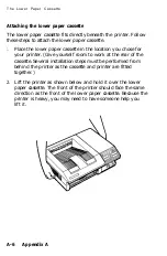
Page 200: ... Cassette 3 Lift the rear cover into place CAUTION When you carry the lower paper cassette hold it by the handles on the left and right side Do not grasp the rear cover or the front side of the cassette Appendix A A 5 ...

Page 201: ...printer Give yourself room to work at the rear of the cassette Several installation steps must be performed from behind the printer as the cassette and printer are fitted together 2 Lift the printer as shown below and hold it over the lower paper cassette The front of the printer should face the same direction as the front of the lower paper cassette Because the printer is heavy you may need to ha...

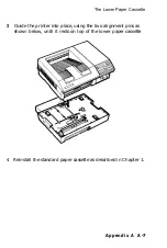
Page 202: ...r Cassette 3 Guide the printer into place using the two alignment pins as shown below until it rests on top of the lower paper cassette 4 Reinstall the standard paper cassette as described in Chapter 1 Appendix A A 7 ...

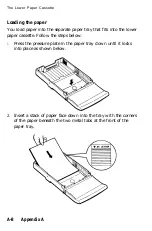
Page 203: ... into the lower paper cassette Follow the steps below 1 Press the pressure plate in the paper tray down until it locks into place as shown below 2 Insert a stack of paper face down into the tray with the corners of the paper beneath the two metal tabs at the front of the paper tray A 8 Appendix A ...

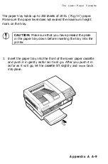
Page 204: ...k on the tray CAUTION Make sure that you have pressed the plate in the paper tray down before inserting the tray into the printer 3 Insert the paper tray into the front of the lower paper cassette and push it in gently as far as it will go After you push it in as far as it will go let the cassette lift slightly and move back into place Appendix A A 9 ...

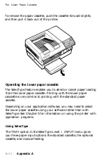
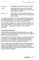
Page 205: ...he lower paper casssette is very similar to printing with the standard paper cassette Depending on your application software you may need to select the lower paper cassette using your software rather than with SelecType See Chapter 5 for information on using the printer with application programs Using SelecType The TRAY option in the SelecType Level 1 INPUT menu gives you three paper input options...

Page 206: ... from your lower paper cassette see the following section on using software commands Using software commands There are special software considerations related to lower paper cassette use Also see Chapter 5 for more information on using the printer with application programs Some application programs can select either cassette directly from the program If your application program does not support tw...

Page 207: ...assette as described below 1 Turn off the printer and unplug the power cord from the outlet 2 Remove the standard paper cassette and the optional face up tray if installed from the printer 3 Grasp the printer by the openings at the bottom right and left side of the printer and gently lift the printer off all the way as shown below A 12 Appendix A ...

Page 208: ...irt from its surface with a soft cloth dampened with alcohol 5 Directly behind the metal rollers locate the short rubber roller as shown below Turn the roller and wipe the surface with a clean damp cloth Allow the roller to dry completely 6 Replace the printer on the lower paper cassette as described earlier in this chapter Appendix A A 13 ...

Page 209: ...ing the face up output tray You must first attach the drive unit to the rear of the printer and then attach the tray to the drive unit WARNING If the printer has been used recently the rear of the printer may be hot Let it cool before you remove the printer s rear cover Note When this tray is installed and you open the printer cover the face up tray touches the desktop and the paper support falls ...

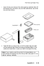
Page 210: ...ce up tray Drive unit 2 Take the face up output tray out of the plastic bag and peel off the packing tape Place the packing materials back in the carton and save them in case you need to transport the tray Note If you need to pack the printer for transportation you must remove the face up tray from the printer and pack it in its original packing materials Appendix A A 15 ...

Page 211: ...ear cover or the face up output tray drive unit is installed You may cause mechanical failure 4 Using the screwdriver provided unscrew the four screws at the rear of the printer and remove the rear cover Save the screws for use in the next step and store the rear cover in a safe place A 16 Appendix A ...

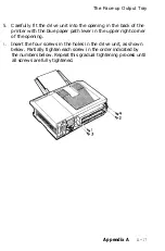
Page 212: ...h the blue paper path lever in the upper right corner of the opening 6 Insert the four screws in the holes in the drive unit as shown below Partially tighten each screw in the order indicated by the numbers below Repeat this gradual tightening process until all screws are fully tightened Appendix A A 17 ...

Page 213: ...low Notice that the tray when installed is nearly vertical as shown in the illustration at the bottom of this page The printer is factory set for face down output on top of the printer To set the printer for face up delivery move the paper path lever located on the drive unit to the FACE UP position as shown below A 18 Appendix A ...

Page 214: ...up tray from the printer for transportation or other purposes follow the steps below 1 Remove the face up tray from the drive unit 2 Using a screwdriver remove the four screws from the drive unit and remove the drive unit 3 Replace the rear cover with the four screws CAUTION Never turn on the printer unless the rear cover or the face up tray drive unit is installed You may cause mechanical failure...

Page 215: ...screwdriver If you have questions about installing the board contact your dealer for assistance WARNING High voltages are present inside the printer when the power is on Do not attempt to remove the controller board unless the printer is turned off and the power cord is unplugged Also try not to touch any contacts on the circuit board of the printer because many of the components can be destroyed ...

Page 216: ... screws located at the corners of the metal bracket as shown below Keep the screws in a safe place 4 Press back on the two levers to release the controller board from the printer as shown below The board pops forward slightly when released Appendix A A 21 ...

Page 217: ...rinter Then set it on a clean stable surface 6 Locate mating connector CN5 on the controller board Lower the memory expansion board into position as shown below and carefully insert the connector on the board into the mating connector 7 Secure the board with the screws provided A 22 Appendix A ...

Page 218: ...ently slide the board about halfway into the printer Also move the white levers so that they point straight up and down as shown below 9 Now slide the controller board completely into the printer Do not touch the two white levers as you do this because they pivot outward as the board locks into place If the controller board does not fit smoothly into the printer do not force it Remove it and check...

Page 219: ... board gently to make sure that it is seated firmly inside the printer Then secure the board with the four retaining screws as shown below 11 Make sure the power is off the 0 side of the switch is down then reconnect the power cord A 24 Appendix A ...

Page 220: ...bed in Chapter 2 Look at the bottom of the start page just above EPSON EPL 7500 You should see the following ramsize 6291456 This shows that the memory board is functioning correctly If the ramsize number is lower than the one shown above turn off the power and remove the board then reinstall it If the ramsize number is still incorrect see your dealer or a qualified service person Appendix A A 25 ...

Page 221: ...Appendix B Character Samples PostScript Mode B 2 Resident bitmap fonts B 2 Resident outline fonts B 3 HP Emulation Mode B 5 Appendix B B l ...

Page 222: ... as point size and weight Outline fonts are defined by mathematical equations that give you a range of possibilities not available with bitmap fonts You can change several of the font attributes of outline fonts by using software or printer commands Resident bitmap fonts The following bitmap fonts are permanently resident in the printer s ROM Times Roman 10 points Helvetica 10 points Courier 12 po...

Page 223: ... Italic Times Bold Italic Helvetica Helvetica Bold Helvetica Oblique Helvetica Bold Oblique Symbol ITC Avant Garde Book ITC Avant Garde Book Oblique ITC Avant Garde Demi ITC Avant Garde Demi Oblique ITC Bookman Demi ITC Bookman Demi Italic ITC Bookman Light ITC Bookman Light Italic Helvetica Narrow Helvetica Narrow Bold Helvetica Narrow Bold Oblique Helvetica Narrow Oblique New Century Schoolbook ...

Page 224: ...PostScript Mode Palatino Roman Palatino Bold Palatino Italic Palatino Bold Italic ITC Zapf Chancery Medium Italic ITC Zapf Dingbats B 4 Appendix B ...

Page 225: ...on Mode The resident bitmap fonts listed on page B 2 are also available in HP emulation mode See page B 2 for print samples To select a font you can use your application program or printer commands Appendix B B 5 ...

Page 226: ...nters and software baud rate A measure of the speed of data transmission It is used when setting a serial interface on a computer and printer binary See number systems bit A binary digit 0 or l which is the smallest unit of information used by a printer or computer See also number systems bitmap font A font that has already been defined with specific attributes such as size and weight See outline ...

Page 227: ...e return or line feed decimal See number systems default A value or setting that takes effect when the equipment is turned on reset or initialized download A way of transferring information from a computer to a printer download font A font that is loaded into the printer s memory from an outside source such as a computer dpi Dots per inch This is a measure of print resolution driver The part of an...

Page 228: ...cted portions of a revolving photosensitive drum Toner is then attracted to the exposed areas of the drum to form a mirror image of the page to be printed The toner adhering to the drum is then transferred to the surface of the paper where it is fused in place using a process combining heat and pressure engine The part of the printer that includes the electrophotographic processing unit engine con...

Page 229: ...hat is wider than it is high and is useful for such purposes as printing spreadsheets LCD Liquid Crystal Display The screen on the control panel that displays messages memory The part of the printer s electronic system that is used to store information Some information is fixed and is used to control how the printer operates Information that is sent to the printer from the computer such as downloa...

Page 230: ...m A binary digit is often called a bit any decimal number between 0 and 255 can be expressed by an eight bit binary number off line When the printer is off line it cannot communicate with the computer on line When the printer is on line it can communicate with the computer orientation Refers to the direction in which characters are printed on a page This direction is either portrait text printed a...

Page 231: ...mmands that determines how data sent from the computer is interpreted and acted upon Printer modes can emulate existing printers The EPL offers three printer modes PostScript I S binary and HP emulation RAM Random Access Memory The portion of the printer s memory used as an input buffer and for storing downloaded fonts and graphic images Information stored in RAM is volatile and is lost when the p...

Page 232: ...nt Also called start page A method of checking the operation of the printer When a test print is performed the printer prints out its current settings and a list of available fonts toner A dry powder like substance composed of resin and pigment Toner is used to form the image during the printing process transfer charger wire A metal wire used to impart a static charge to the paper causing toner pa...

Page 233: ...ing glass lens 6 6 paper feed roller 6 19 printer 6 21 roller in the paper path 6 17 transfer charger wire 6 4 Communications See Interface hardware Computer connecting to the printer 2 16 CONTINUE light 2 3 Controller board reinstalling A 23 removing A 20 specifications 8 9 Control panel buttons 2 4 indicator lights 2 3 LCD 2 2 SelecType 3 4 D Data bits 3 19 Desktop publishing software 5 5 Dimens...

Page 234: ... 5 5 Interface hardware 8 10 AppleTalk connecting 2 16 choosing an 2 21 parallel connecting 2 18 SelecType options 3 16 specifications 8 10 serial connecting 2 22 SelecType options 3 17 specifications 8 13 Internal fonts See Fonts resident L Labels printing 4 3 Laser printer precautions 5 LEVEL 1 light 2 3 LEVEL 2 light 2 3 Lights indicator 2 3 Loading paper standard paper cassette 4 9 optional lo...

Page 235: ...3 4 7 selecting 3 13 4 6 Ozone filter 6 14 8 8 P Paper choosing 4 2 delivery choices 4 6 handling problems 7 34 jams 7 12 7 35 loading 4 9 manual feed 3 10 4 13 printable area 8 5 size 3 11 4 5 specifications 8 4 types of 4 2 7 24 8 4 Paper cassette optional See Lower paper cassette Paper cassette standard installing 1 19 loading 4 9 Paper path selector 4 7 Parallel interface See Interface hardwar...

Page 236: ... 8 9 environmental 8 9 font 8 2 initialization 8 17 mechanical 8 8 options 8 20 paper 8 4 parallel interface 8 10 printer mode 8 2 printing 8 2 serial interface 8 13 Spreadsheets 5 6 STANDBY mode 3 22 Start page 2 6 3 20 Status messages 7 2 Stop bits 3 19 T Test print 2 6 7 18 Toner cleaning spilled 6 20 7 32 Transfer charger wire 6 4 Transparencies printing 4 3 Transporting the printer 6 22 Troub...

Page 237: ...V Ventilation grill 6 15 W Weight paper 8 4 printer 8 8 Index IN 5 ...

Page 238: ...SelecType Map The following menu maps show the possible menus and options available in SelecType mode An asterisk indicates the factory setting See Chapter 3 for a description of each option ...

Page 239: ...TER LEGAL GLT GLG EXECUTIVEPAGE F4 PAPERSIZE OPT TRAY LETTER A 4 A5 B5 HALFLETTER LEGAL GLT GLG EXECUTIVE PAGE F4 OUTPUT F A C E U P FACE DOWN MISCELLANEOUS RESET LEVEL 1 SAVE LEVEL 1 RECOVERY PARTIAL C O M P L E T E LJ AVAIL XXXXXX LJ ALLOCATION NONE 10 100 Note The factory settings of PAPERSIZE STD TRAY and PAPERSIZE OPT TRAY depend on the country ...

Page 240: ... BAUD 36400 BAUD PARITY MARK OR NONE SPACE OR NONE PARITY ODD PARITY EVEN FLOW CONTROL DTR XON XOFF XON XOFF DTR STOP BITS 1 STOP BIT 2 STOP BITS DATA BITS 7 DATA BITS 8 DATA BITS BAUD RATE 300 BAUD 600 BAUD 1200 BAUD 2400 BAUD 4800 BAUD 9600 BAUD 19200 BAUD 36400 BAUD 57600 BAUD PARITY MARK OR NONE SPACE OR NONE PARITY ODD PARITY EVEN STOP BITS 1 STOP BIT 2 STOP BITS DATA BITS 7 DATA BITS 6 DATA ...

Page 241: ...BEEPER STARTPAGE TEST PRINT SAVE LEVEL 2 PAGES XXXX FACTORY RESET ERROR HANDLER BEEPER ON BEEPER OFF STARTPAGE ON STARTPAGE OFF LETTER A 4 ERROR HANDLER ON ERROR HANDLER OFF STANDBY DISALLOWED STANDBY ALLOWED STANDBY ...

Page 242: ......

Page 243: ......

Page 244: ......

Reviews: