


EPSON Stylus PHOTO 895/785EPX
Revision A
Disassembly and Assembly
Disassembly
83
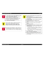
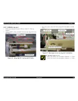
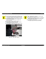
4.
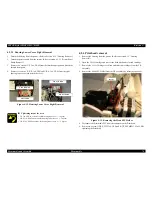
Remove four Hexagon Nuts while holding the CR motor and remove the CR
motor assembly. (Remove two hexagon nuts on the lower side with a one side
open-end wrench)
Figure 4-18. Removing the CR motor
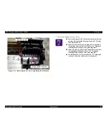
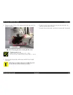
5.
Disconnect the CR motor connector cable from the CN13 on the Main board with
tweezers
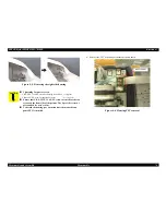
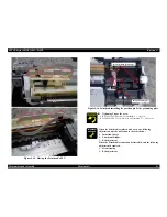
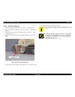
4.2.6 Waste drain ink pad unit removal
1.
Remove the Housing from the printer. (Refer to Section 4.2.1 "Housing
Removal")
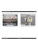
2.
Remove two screws (C.B.S. 3x6, F/ZN and C.B.P. 3x8, F/ZN) and detach the Sub
Left Panel Housing from the printer mechanism. (Detach the stacker at the same
time)
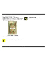
Figure 4-19. Removing the waste drain inkpad unit
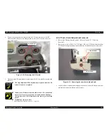
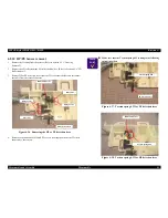
3.
Lift the left side of printer and disengage the hook of waste drain ink pad unit, then
pull out the waste drain ink pad unit to remove.
A D J U S T M E N T
R E Q U I R E D
The Gap adjustment (Bi-d adjustment) is required when the CR
motor is removed or replaced.
Connect the CR motor connector cable to the CN13 on the Main
board. Use of tweezers or pincers is recommended to facilitate
the job, since the CN13 is located near the rear edge of the Main
board.
Tightening Torque for screw
• M3 hexagon nut for the CR Motor: 9 +/- 1 kgf.cm
Hexagon Nuts
C.B.P 3x8 F/ZN
C.B.S 3x6 F/ZN


