


EPSON Stylus Pro 3800/3800C/3850
Revision A
DISASSEMBLY & ASSEMBLY
Disassembly/Assembly Procedure (Group 2)
181
8.
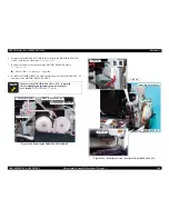
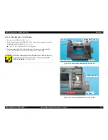
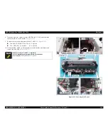
Disconnect the relay connector of the MOTOR ASSY., ASF, and release the
cables from the two cable hooks.
See Figure 4-41.
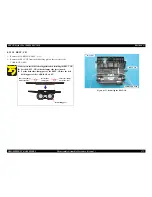
9.
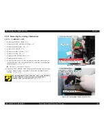
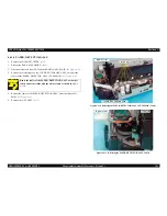
Remove the four screws that secure the ASF, ASSY.
See Figure 4-125.
Two SHAFT, MOUNT, PLATEs: (9 ± 1 kgf.cm)
Two C.B.S. (P4). 3 x 8 screws:
(9 ± 1 kgf.cm)
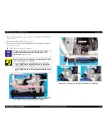
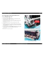
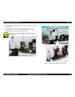
10. Lift up the ASF, ASSY., to disengage the two tabs from the main frame and
remove the ASF, ASSY.
See Figure 4-125.
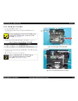
Figure 4-125. Removing the ASF, ASSY.
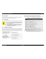
A D J U S T M E N T
R E Q U I R E D
Whenever the ASF, ASSY., is replaced,
the corresponding adjustments must be carried out.
See Chapter 5
"ADJUSTMENT" (p190)
.
SHAFT, MOUNT, PLATE
tab
SHAFT, MOUNT, PLATE
tab
main frame
ASF, ASSY.
Rear side
C.B.S. (P4). 3x8
C.B.S. (P4). 3x8
Summary of Contents for 3800 - Stylus Pro Color Inkjet Printer
Page 1: ...EPSONStylusPro3800 3800C 3850 Large Format Color Inkjet Printer S SERVICE MANUAL SEIJ06007 ...
Page 5: ...Revision Status Revision Date of Issue Description A November 30 2006 First release ...
Page 9: ...C H A P T E R 1 PRODUCTDESCRIPTION ...
Page 35: ...C H A P T E R 2 OPERATINGPRINCIPLES ...
Page 61: ...C H A P T E R 3 TROUBLESHOOTING ...
Page 85: ...C H A P T E R 4 DISASSEMBLY ASSEMBLY ...
Page 190: ...C H A P T E R 5 ADJUSTMENT ...
Page 250: ...C H A P T E R 6 MAINTENANCE ...
Page 262: ...C H A P T E R 7 APPENDIX ...
Page 279: ......
Page 280: ......
Page 281: ......
Page 282: ......
Page 283: ......
Page 284: ......
Page 285: ......
Page 286: ......


