3.
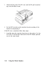
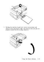
Attach the plug end of the FG wire onto the FG pin located on
top of the interface board.
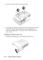
4. Set the DIP switches on the interface board according to the
manual accompanying it.
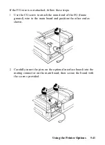
If the FG wire is attached, follow these steps:
1.
Carefully place the interface board next to the printer. Use the
CG screw to connect the round end of the FG (frame ground)
wire to the main board.
5-42
Using the Printer Options
Summary of Contents for 1010
Page 1: ......
Page 2: ...EPSON LQ 510 1010 User s Manual ...
Page 182: ...Chapter 7 Troubleshooting Printing 7 2 Paper Handling 7 7 Options 7 10 Troubleshooting 7 1 ...
Page 249: ...Appendix Proportional Width Table A 2 Character Sets A 6 A 1 ...
Page 257: ...PC 865 Norway CODE 0 1 2 3 4 5 6 7 8 9 A B C D E F 0 1 2 3 4 5 6 7 8 9 A B C D E F A 9 ...
Page 271: ......
Page 274: ......
Page 275: ......
Page 276: ......
Page 278: ......
Page 279: ......


