


Section 6: Using the Epilog Dashboard
53
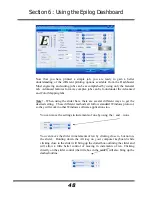
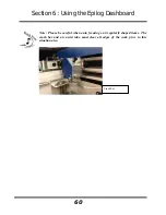
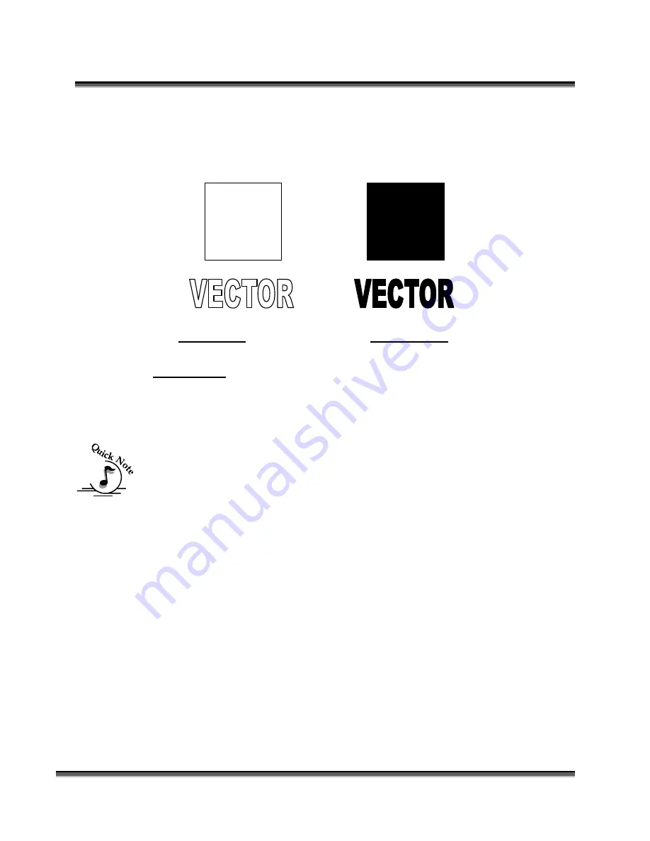
When using vector mode, it is necessary to design your job to give the intended
result. Objects and text should be unfilled and drawn with the thinnest possible
outline (other than zero), as shown below. A .001 inch (.025 mm) is
recommended.
CORRECT
Vector setup
INCORRECT
Vector setup
Combined
Combined mode is used when you want to incorporate both Raster and Vector
functions in the same job setup. When you are in Combined mode, all Raster
operations will be performed first, with the Vector operations second.
Note on Vectors:
If you are in Vector or Combined mode, all thin lines will be
vector cut! This can be disconcerting because even if the lines are not visible in
your artwork they will still cut. Usually, this happens when incorporating a
clipart image that has hidden lines that are not readily apparent. Please refer to
the
Quick Start & Easy Setup
section of this manual for an illustrated explanation
of how this can affect your work.
In addition to speed, power and frequency, there are two additional parameters for
vector mode:
Slow Cutting:
Slow Cutting
reduces all speed settings by ½. For example, a speed setting of 10
without Slow Cutting select will move twice as fast as a setting of 10 with Slow
Cutting selected. In essence, Slow Cutting provides an alternative set of speed
parameters that are ½ the speed as the standard settings. Slow Cutting mode will
most often be used for very slow cutting applications when the standard settings
are too fast. Most users will rarely use Slow Cutting mode, but it adds an
additional mode of operation for unusual or demanding applications.
Summary of Contents for Fusion 13000
Page 2: ...ii THIS PAGE WAS INTENTIONALLY LEFT BLANK ...
Page 4: ...Contents at a Glance iv THIS PAGE WAS INTENTIONALLY LEFT BLANK ...
Page 8: ...Table of Contents viii INDEX 195 THIS PAGE WAS INTENTIONALLY LEFT BLANK ...
Page 10: ...Fire Warning x SEE PREVIOUS PAGE ...
Page 14: ...Introduction xiv THIS PAGE WAS INTENTIONALLY LEFT BLANK ...
Page 15: ...1 Manual Epilog Laser Setup ...
Page 16: ...2 THIS PAGE WAS INTENTIONALLY LEFT BLANK ...
Page 26: ...Section 1 Safety 10 ...
Page 27: ...Section 1 Safety 11 ...
Page 28: ...Section 1 Safety 12 THIS PAGE WAS INTENTIONALLY LEFT BLANK ...
Page 41: ...Section 3 Getting Started 11 THIS PAGE WAS INTENTIONALLY LEFT BLANK ...
Page 44: ...Section 4 Installing the ECC 14 ...
Page 51: ...Section 4 Installing the ECC 21 THIS PAGE WAS INTENTIONALLY LEFT BLANK ...
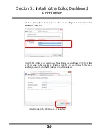
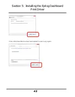
Page 58: ...Section 5 Installing the Epilog Dashboard Print Driver 28 10 Click on Update Driver ...
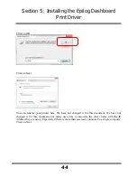
Page 68: ...Section 5 Installing the Epilog Dashboard Print Driver 38 Click on Add Local Printer ...
Page 108: ...Section 6 Using the Epilog Dashboard 78 THIS PAGE WAS INTENTIONALLY LEFT BLANK ...
Page 109: ...79 Manual Basic Operations ...
Page 110: ...80 THIS PAGE WAS INTENTIONALLY LEFT BLANK ...
Page 130: ...Section 8 Using the Front Control Panel 100 THIS PAGE WAS INTENTIONALLY LEFT BLANK ...
Page 136: ...Section 9 Using the ECC Epilog Control Center 106 THIS PAGE WAS INTENTIONALLY LEFT BLANK ...
Page 148: ...Section 10 Standard Optional Machine Features 118 ...
Page 152: ...Section 11 Engraving Machine Cleaning 122 Crash Bar and locating pins ...
Page 160: ...Section 11 Engraving Machine Cleaning 130 ...
Page 184: ...Section 13 Material Engraving Techniques 154 THIS PAGE WAS INTENTIONALLY LEFT BLANK ...
Page 191: ...161 Manual Technical Support Troubleshooting and Specifications ...
Page 192: ...162 THIS PAGE WAS INTENTIONALLY LEFT BLANK ...
Page 194: ...Section 15 In Case of Difficulty 164 THIS PAGE WAS INTENTIONALLY LEFT BLANK ...
Page 200: ...Section 16 Specifications 170 THIS PAGE WAS INTENTIONALLY LEFT BLANK ...
Page 208: ...APPENDIX A 178 THIS PAGE WAS INTENTIONALLY LEFT BLANK ...
Page 218: ...Appendix C Additional Dashboard Instructions 188 ...


