TUTORIALS
Controlling a Multi-Welder/Cascade
207 |
P a g e
Copyright © 2021 BF ENTRON and/or its affiliates. All rights reserved
Product Model:
iPAK2v2
Firmware Version:
V2.10
May 22 | Doc No 700253-2
10.3.2
Assign Electrode to a Transformer
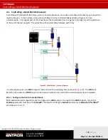
The relationship between an electrode and the transformer must be defined. Once
Transformers
have been assigned to
Electrodes
,
Electrodes
can be assigned to weld programs.
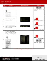
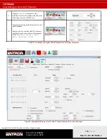
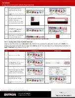
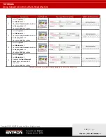
Table XX shows how to define the Transformer/Electrode relationship in the
Electrode
tab of
NetFlash™.
The
Electrode
can then be defined for the Weld Program in the
Program
tab of
NetFlash™.
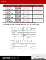
PROGRAM
ELECTRODE PARAMETERS
PROGRAM PARAMETERS
Firing assignment
1
PROGRAM 0
ELECTRODE 0
TRANSFORMER 0
2
PROGRAM 1
ELECTRODE 1
TRANSFORMER 1
3
PROGRAM 2
ELECTRODE 2
TRANSFORMER 2
4
PROGRAM 3
ELECTRODE 3
TRANSFORMER 3
Table 80: Defining Electrode/Transformer Relationship
10.3.3
Programming a Multi-Welder/Cascade Sequence
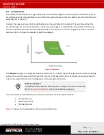
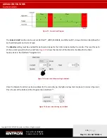
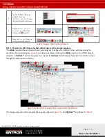
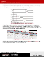
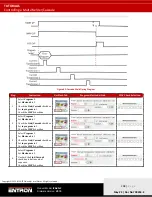
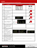
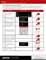
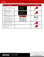
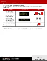
A Multi-Welder/Cascade weld timing sequence is shown in
. The sequence has a single start input and then a
defined series of weld programs are executed one after the other using different transformers. The WAV output is the
same for each weld program. The step-by-
step instructions to program this sequence using NetFlash™ are defined in
Table XX.

