


25
© 2017 Energreen Srl
Professional machinery
11
12
13
14
16
15
18
17
19
20
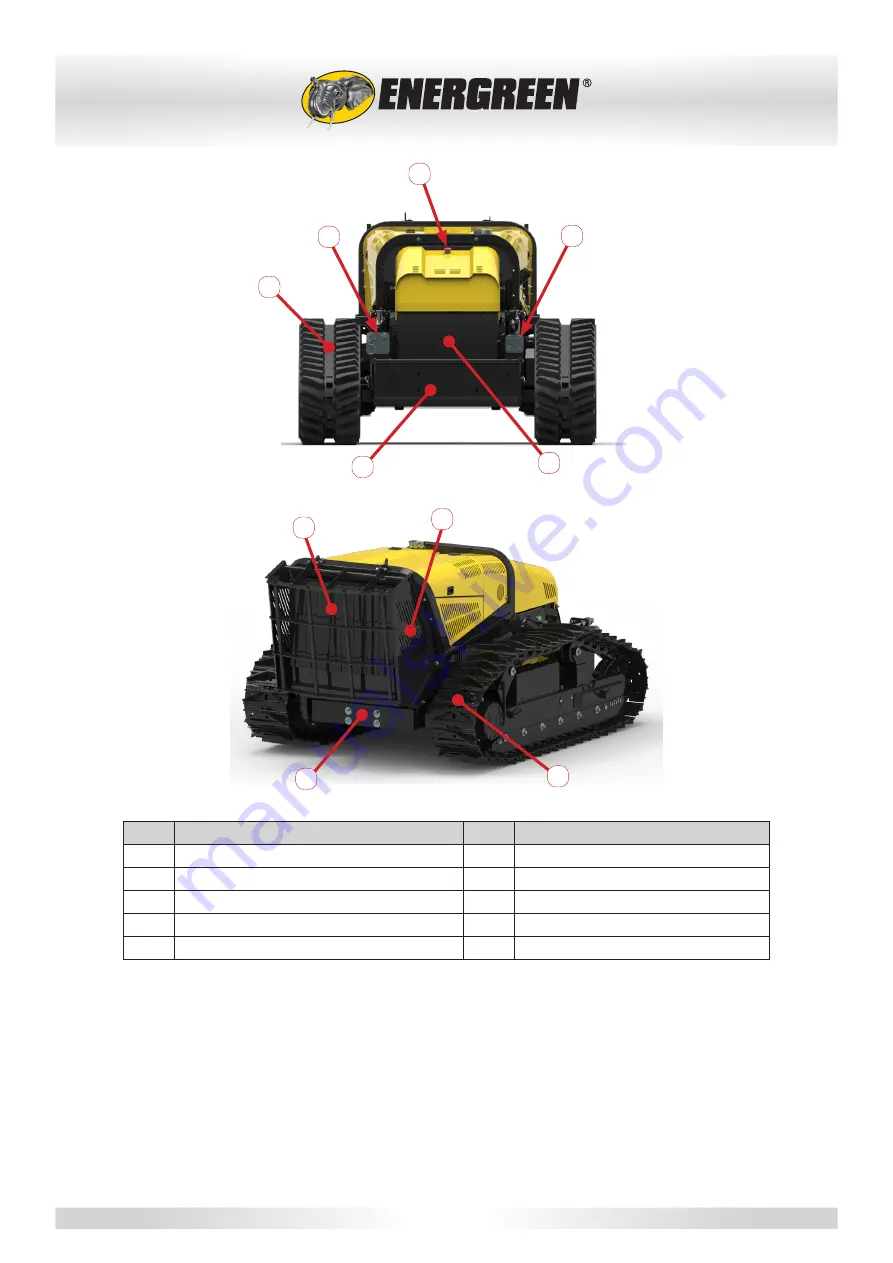
Pos.
Description
Pos.
Description
11
Emergency button
16
Rapid milling machine connectors
12
High pressure quick couplings
17
Radiator grille guard
13
Rubber tracks
18
Radiator casing
14
Lifting device / Equipment mounting plate
19
Ballast
15
Hydraulic oil tank
20
Steel track
Summary of Contents for RoboMAX
Page 2: ......
Page 104: ...96 2017 Energreen Srl Professional machinery 12 NOTES...