


Theory of Operation
P/N 400274-01 Revision A7
19
Maximum Master Velocity
For every set of Master and Follower cycle parameters, the user must
limit the maximum velocity of the Master so that the maximum velocity
of the Follower is not exceeded. This is critical for product lengths
shorter than the Follower Cycle Length.
(
)
Maximum Master Velocity
MAV
FVS / MVS * 2 - WR
=
Where:
MAV
= Maximum Allowable Velocity of the Follower from the Limits
screen.
WR
= Working Ratio.
FVS
= Follower Variable Segment =
Follower Cycle Length - Working Segment.
MVS
= Master Variable Segment =
Master Cycle Length - (Working Segment / Working Ratio).
Note:
The above equation reflects ideal conditions and the user must
reduce the calculated Maximum Master Velocity due to the
effects of inertia, friction, encoder slippage, sensor, mechanical
issues to allow enough velocity headroom for any motion
corrections. Usually, this velocity reduction needs to be
approximately 20 percent.
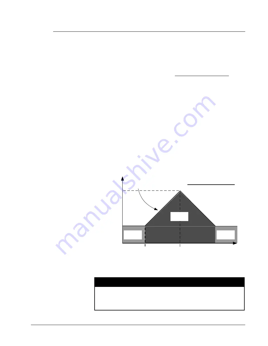
V
Peak
V
Working Ratio
Velocity
Time
T
Peak
T
Working Segment End
V
Peak
-
V
Working Ratio
T
Peak
-
T
Working Segment End
Follower Acceleration =
VARIABLE
SEGMENT
WORKING
SEGMENT
WORKING
SEGMENT
0
Figure 12
Variable Segment Acceleration
At the Maximum Master Velocity, V
Peak
= MAV.
WARNING!
When sizing a system, keep in mind the velocity and acceleration of
the Follower during the variable segment for the shortest product
length because the Follower acceleration and deceleration rates are
not controlled by PCX Limits.


