


Chapter 2 Single UPS Installation And Commissioning 21
Liebert
®
ITA 5kVA And 6kVA UPS User Manual
Paralleled address
Control port
Input switch
230/400Vac-40A
In
te
llis
lo
t
Battery port
192Vdc 27A
-
PE
+
UPS
B
at
tery
m
odule 1
B
at
tery
m
odule 2
B
at
tery
m
odule 3
Battery cable A
Accessory cable of the battery module
Accessory cable of the battery module
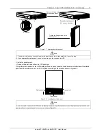
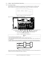
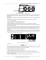
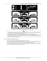
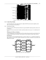
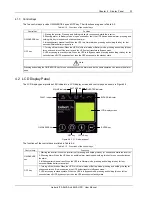
Figure 2-31 Cable connection for the long back-up UPS and the battery module
Note
1. If the battery cable is not essential, you can plug the battery cable. After that, please restore the protective cover of the battery
port on the UPS to its original place immediately to avoid electrical shock;
2. The battery cable A is not only the accessory of the standard UPS, but also the option of the long back-up UPS;
3. The maximal allowable charge current of the standard battery module is 2.16A, and the maximal allowable charge current of the
long back-up UPS is 4A, therefore when the standard battery module is used to connect with the long back-up UPS, the number of
the standard battery modules is not less than 3.
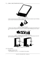
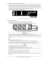
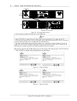
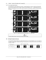
2.5.3 Connecting 10A Charger Cables
The 10A charger is optional; its cable connection procedures are as follows:
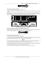
1. Take out the 10A charger cable (DB9) from its package, remove the protective cover of the control port on the rear
panel of the 10A charger (see Figure 2-27), and insert one end of the cable into the control port.
2. Remove the protective cover of the control port on the rear panel of the UPS, and insert the other end of the cable
into the control port of 10A charger, as shown in Figure 2-27.


