


16 Chapter 2 Single UPS Installation And Commissioning
Liebert
®
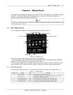
ITA 5kVA And 6kVA UPS User Manual
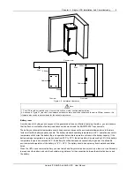
2.5.1 Connecting I/O Cables
The power cables of the UPS should be connected through the I/O terminal block located on the UPS rear panel.
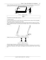
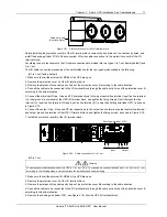
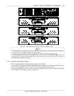
Remove the protective cover A of the I/O terminal block shown in Figure 2-15 to reveal the I/O terminal block.
Figure 2-20 Protective cover A of the I/O terminal block
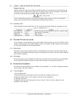
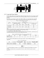
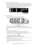
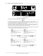
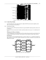
Figure 2-16 gives the terminal layout of the I/O terminal block.
Input neutral line terminal
Input live line terminal (U)
Output neutral line terminal
Output live line terminal
Input ground line terminal
Output ground line terminal
Input live line terminal (V)
Input live line terminal (W)
Input live line terminal (U1)
Figure 2-21 Terminals layout of the I/O terminal block
Note
1. Do not reverse the input neutral line and live line.
2. Do not use a wall socket to feed power to the UPS. Otherwise, the socket may be burned.
3. Connect the output neutral line and live line and ground line correctly and reliably. For the sake of safety, the ground line must
be connected firstly.
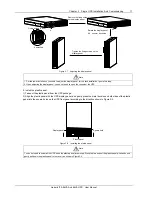
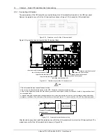
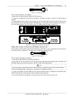
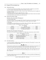
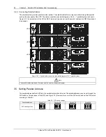
4. Install a three-pole or quadrupole linkage breaker on the mains input neutral line and live line to facilitate cutting power under
emergency conditions. Use correct power distribution method (see Figure 2-17) to ensure safety of the UPS and user equipment.
Input live line
Input neutral line
U
P
S
Load
V
N
E
Three-pole or quadrupole
linkage breaker
U
W
Output live line
Output neutral
line
Figure 2-22 Correct power distribution method
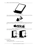
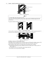
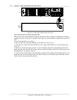
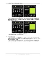
After the cable connection, install the protective cover B of the I/O terminal block to protect the I/O terminal block. The
protective cover B of the I/O terminal block is shown in Figure 2-18.


