


Chapter 1 Product Introduction 3
Liebert
®
ITA 5kVA And 6kVA UPS User Manual
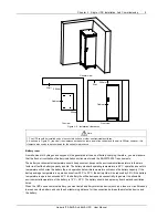
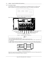
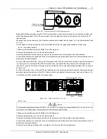
USB port
Ventilation hole 10A charger
control port
Parallel port (With protective cover) DIP switch (With protective cover) Input MCB Battery port
I/O terminal block
(With protective cover)
Intelligent card slot
(With protective cover)
Figure 1-3 UPS rear panel
Note
Non-authorized personnel are prohibited from opening the UPS chassis cover.
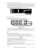
1.4 Operating Principle
The operating principle of the UPS is shown in Figure 1-4.
I/O filter
Rectifier/PFC
Inverter
DC/DC
Battery input
Mains
input
UPS
output
Bypass
Internal charger
Figure 1-4 UPS operating principle
1. The UPS is composed of mains input, I/O filter, rectifier/PFC, DC/DC boost, inverter, bypass, internal charger,
battery input and UPS output.
2. When the mains is normal, close the bypass MCB, and the internal charger will charge the battery. Before turning on
the UPS, the output voltage is zero. After the UPS is turned on, the electronic transfer switch connects the inverter to
the load, and the mains supplies DC power to the inverter through the rectifier/PFC circuit. The inverter then converts
DC power into pure sine wave AC power, and supplies the AC power to the load through the electronic transfer switch.
3. When the mains is abnormal, the rectifier/PFC circuit boosts the battery voltage and supplies it to the inverter. The
inverter then converts it into pure sine wave AC power, and supplies the AC power to the load through the electronic
transfer switch.
4. After the mains restores, the UPS will automatically transfer from Battery mode to Normal mode, the mains supplies
DC power to the inverter through the rectifier/PFC circuit, and then the electronic transfer switch supplies the AC
power to the load.
1.5 UPS State And Operation Mode
The UPS state and operation mode include: Normal mode, Bypass mode, Battery mode, ECO mode, Fault state and
Maintenance Bypass mode.
The operation schematic diagrams of Normal mode, Bypass mode, Battery mode and Maintenance Bypass mode are
shown in Figure 1-5.
Note
Only when the UPS output power distribution unit (POD for short) is configured, can the Maintenance Bypass mode be valid.