34 • High Pressure CO2 Controller Installation and Operation Manual
T1 button for EXIT.
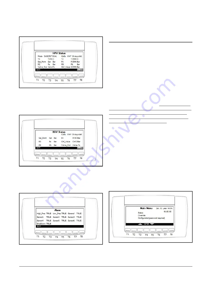
HPV Status Screen:
Figure 10-5
- HPV Status Screen
This screen gives you the HPV status of performance,
setpoints, and control input values. To return to the Status
screen, press the T1 button for EXIT.
BGV Status Screen:
Figure 10-6
- BGV Status Screen
This screen gives you the BGV status of performance,
setpoints, and control input values. To return to the Status
screen, press the T1 button for EXIT.
Alarm Status Screen:
Figure 10-7
- Alarm Status Screen
This screen gives you the alarm status values if the
alarm is true/active or false/not active. To return to the
main Status screen, press the T1 button for EXIT.
10.2 Configuration Setup
Screen
The Configuration setup screens are password pro-
tected. In the Configuration screens, the user will have a
menu listing of setting up the control valve configuration
parameters, XEV20D valve settings, input + output con-
figuration, and general configuration.
Under general configuration, it will have a menu with
the MODBUS address, baud rate, screens update, time and
date, Sensor type (Emerson Retail Solutions or Dixell),
engineering units, pressure transducer settings, shutdown
delay and the factory default reset.
Note: Before connect-
ing the High Pressure CO2 controller to E2, please make
these preference changes since it will not be available
through E2 once the device is online and configuration
can only be made via the E2 once online
.
The valve configuration screen will have all of the set-
points parameters, PID settings, safeties, and calibration
feature for the valves (HPV/BGV).
The input and output configuration screen will define
the type of sensor function and the polarities of the digital
inputs and outputs. It will also provide the inputs offset.
The XEV20D configuration screen is for setting up the
valve specification if the XEV20D is chosen to drive the
HPV valve and/or BGV valve.
10.2.1 Main Menu to Configuration
Screens
To enter the Configuration Screens, you will need to be
on the Main Menu to enter the password.
Figure 10-8
- Main Menu Screen
Main Menu screen. To enter the Configuration screen,
Summary of Contents for 818-9010
Page 1: ...026 1731 Rev 0 01 DEC 2014 High Pressure CO2 Controller Installation and Operation Manual ...
Page 2: ......
Page 4: ......
Page 19: ...Figure 3 1 MODBUS Networking 13 ...
Page 45: ...Figure 10 29 Override Screen 39 ...
Page 49: ...Figure 12 2 High Pressure CO2 Device Wiring and Network Connection 43 ...


