P 2500 - P 5000
36
6. Now insert the second securing piece.
7. Push both securing pieces against the anchor plate and secure them with
the screws.
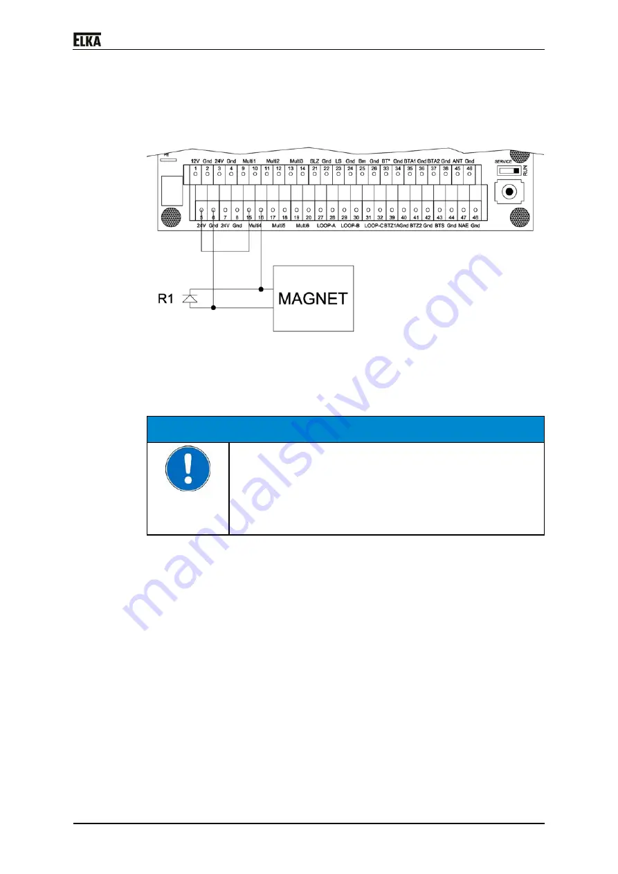
Connecting the electromagnet in the barrier:
Drawing 24
Following the connection of an electromagnet as well as the required
parameter changes in the controller are described. As an example the multi-
functional relay 4 (MULTI4) and as power supply for the standard
electromagnet the internal 24Vdc of the MO 24 is used.
CAUTION!
Over-voltage when switching off an inductive DC load!
Defect of the controller or the external (on-site) DC voltage
source by overvoltage!
Always connect the free-wheeling diode R1 (type
1N4004), as shown in the drawing, when using an
electromagnet.
1. Connect the electromagnet to the terminal row, as shown in the drawing.
Use a minimum cable cross-section of AWG 16. The cable length shall not
exceed a length of 65.61ft.
2. Connect the multi-functional relay 4 to 24Vdc.
3. Activate the pre-warning time in the learning sequence of the controller
MO 24 under sequence point P302. Select a time longer than 1.5 seconds.
4. Activate the multi-functional relay 4 in the learning sequence under
sequence point P504. Select the operating mode “10” - The multi-
functional relay is activated, when the barrier is closed. During the pre-
warning before opening the relay is already switched off.
Procedure:
1. The barrier is closed. On receipt of a signal to open the multi-relay is
switched off and it loses the residual magnetism during the pre-warning
time.
2. The barrier opens after the set pre-warning time (P302) has elapsed.
3. The barrier is open. After a closing impulse the multi-functional relay (the
magnet) is switched on only when the end position CLOSED is reached.
Summary of Contents for P 2500
Page 14: ...P 2500 P 5000 13 4 Declaration of incorporation Drawing 2 ...
Page 20: ...P 2500 P 5000 19 7 2 Mounting dimensions Drawing 3 ...
Page 47: ...P 2500 P 5000 46 8 4 Circuit diagram Drawing 34 ...
Page 48: ...P 2500 P 5000 47 Drawing 35 ...
Page 49: ...P 2500 P 5000 48 Drawing 36 ...
Page 50: ...P 2500 P 5000 49 Drawing 37 ...
Page 51: ...P 2500 P 5000 50 Drawing 38 ...
Page 52: ...P 2500 P 5000 51 Drawing 39 ...
Page 55: ...P 2500 P 5000 54 10 Layout exploded drawing Drawing 41 ...


