7
Technical Description of the Device
132
Unscrew the connector nut (3) and insert it into the holder in the cover (4).
Remove the blind cap (5) at the bottom of the enclosure.
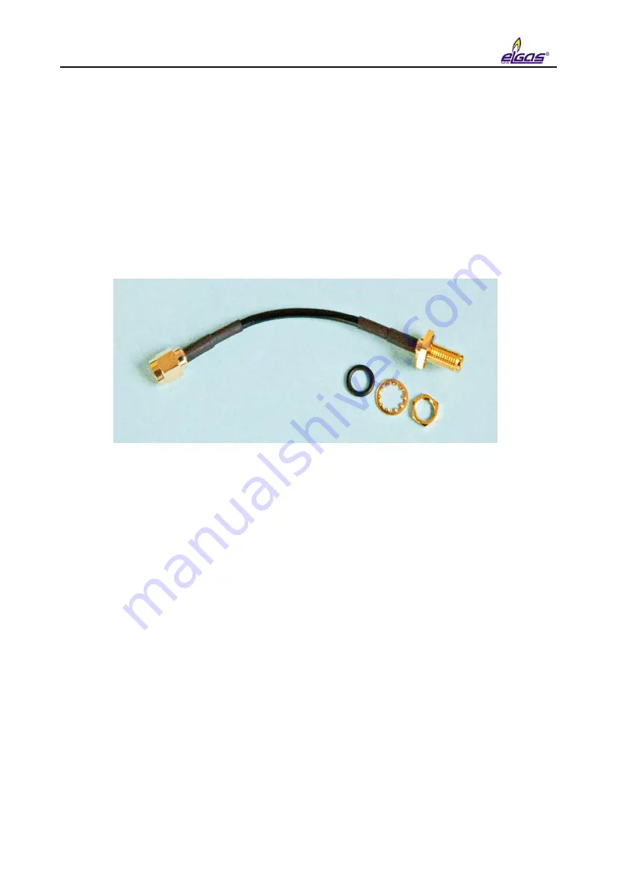
Install the HF cable reducer. Insert the panel connector of the HF cable reducer with the
rubber O-ring into the blind cap opening (5) and fasten it outside the enclosure using a nut
and a washer. Tighten the nut gently (0.7 Nm), remember to hold the fixed part of the
connector with the key. Then connect the other end of the HF cable reducer to the
connector on the modem board.
Put the SIM card cover (1) back and close it.
Reconnect the modem battery connector.
Connect the external power supply to the PWR2 terminals of the external power supply of
the modem.
Fig. 64 External antenna cable adapter
7.8 Software
The device software (firmware, FW) is divided into 3 parts. The first part ("Loader") is used to
ensure that the firmware is uploaded when it is updated.
The second part of the firmware ("Metrolog") includes software for the metrological functionality of
the device, display control and keypad control, metrological data security routines and control
mechanisms for error statuses detection.
The third part of the firmware ("App") contains the rest of the firmware - communication protocols,
communication channel management, superstructure functionality, etc.
Each part of the FW is identified by the version number and the checksum. The version
designation is stored in the form of a string; it is a decimal number with two decimal places. The
version and checksum "Loader" and "Metrolog" are specified in the certificate, versions can only
be modified by the notified body with official approval. Changing in version unit number means a
major change, changing the decimals indicates a version with minor changes or bug fixes.
Summary of Contents for DATCOM
Page 38: ...3 Technical Parameters 36 ...
Page 50: ...5 Installation and Commissioning 48 Fig 7 Examples of data plates ...
Page 83: ...5 Installation and Commissioning 81 Fig 37 Communication via RS232 RS485 using B RS module ...
Page 115: ...7 Technical Description of the Device 113 Fig 57 Functional diagram of ELCOR ...
Page 116: ...7 Technical Description of the Device 114 Fig 58 Functional diagram of ELCORplus ...
Page 122: ...7 Technical Description of the Device 120 Fig 61 Modem replacement ...
Page 159: ...10 Communication with the Device 157 packet ...
Page 174: ...12 Accessories 172 Fig 78 ELCORplus example of use of external modules ...
Page 213: ...Appendix 3 Compass Data Export 211 Preview of generated document ...
Page 215: ...Appendix 3 Compass Data Export 213 3 Export to XLS 4 Export to TXT DOC ...
Page 216: ...Appendix 3 Compass Data Export 214 ...
Page 217: ...Appendix 3 Compass Data Export 215 5 Export of graph ...


