


Sealed System
7-20
Evacuating the System
To achieve the required levels of evacuation, a properly
maintained two stage vacuum pump in good condition
is required. It is absolutely essential to maintain your
vacuum pump according to the manufacturer’s
instructions, including required oil changes at the
recommended intervals. Vacuum pump oil should
always be changed after evacuating a contaminated sys-
tem. Vacuum pump performance should be checked
periodically with a micron gauge.
1. Ensuring that the valve on the charging cylinder is
closed, start the vacuum pump. Slowly open both
manifold valves, counterclockwise, for two full turns.
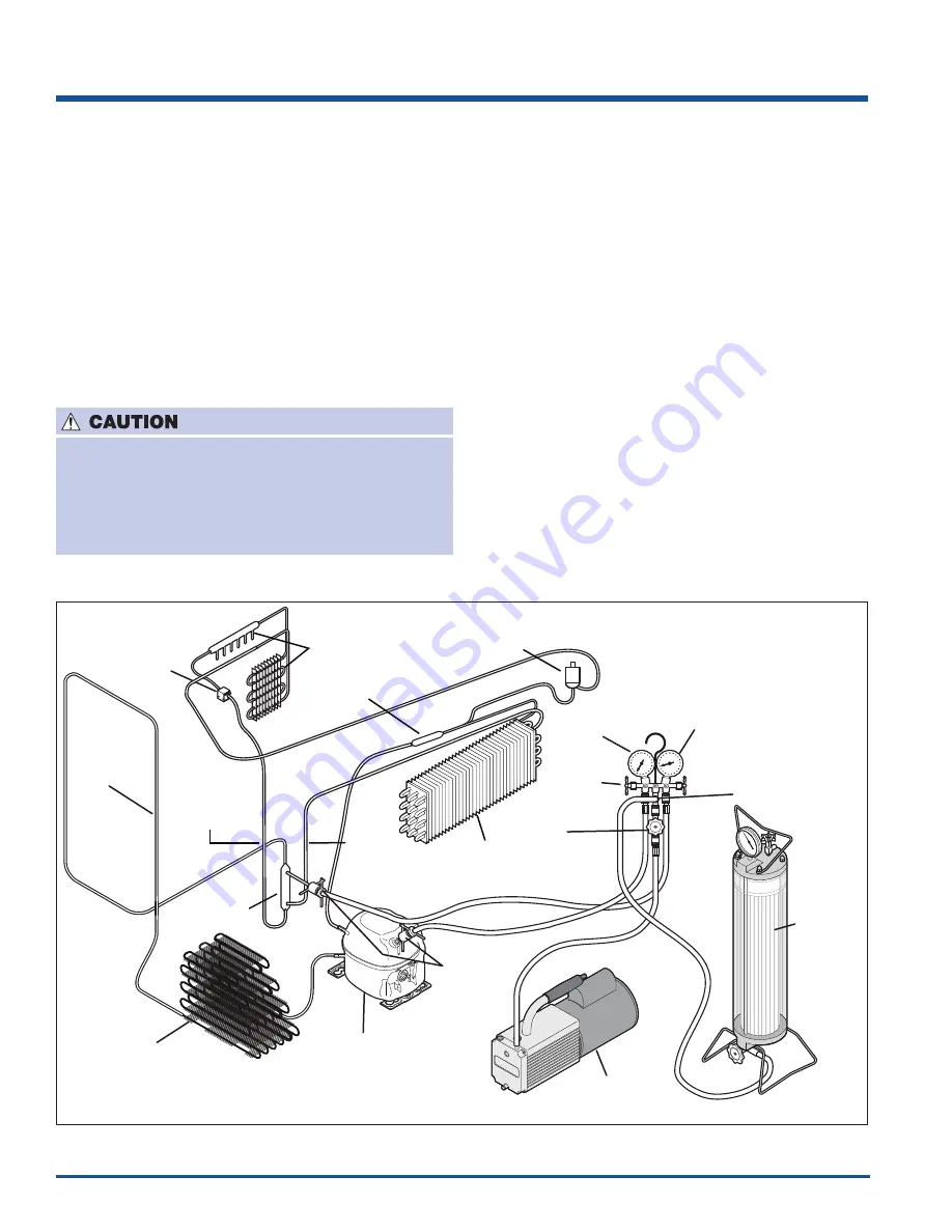
Condenser
Hot Tube
Filter Drier
Compressor
EEV
Valve
Evaporator
Ice Maker
Cap Tube
Ice Maker
Evaporator
Cap Tube
Freezer
Evaporator
Accumulator
Freezer
Evaporator
Pressure
Regulator
2 Stage
Vacuum Pump
Heated
Charging
Cylinder
Process
Tube
Adapters
Pressure
Gauge
Compound
Gauge
Gauge
Manifold
T-Fitting
Hand Shutoff
Valve
Figure 7-21. Installation of Recovery Equipment
If high vacuum equipment is used, just crack both
manifold valves for a few minutes and then open
slowly for the two full turns counterclockwise.
This will prevent the compressor oil from foaming
and being drawn into the vacuum pump.
2. Operate vacuum pump for 30 minutes to a minimum
of 29.5 inches of vacuum or until a vacuum of 600
microns is obtained.
3. Close the manifold valve connected to the vacuum
pump. Watch the compound gauge for several
minutes. If the reading rises, there is a leak in the
system, go to step 4. If no leak is indicated, stop the
vacuum pump. The system is now ready for
charging.
4. If a leak is indicated, stop the vacuum pump and
introduce a small charge of refrigerant into the
system by cracking the valve on the bottom of the
charging cylinder until the system is pressurized to
40 or 50 lbs. P.S.I.
5. Leak test the low side. Run the compressor for
a few minutes and leak test the high side. When
leak is found, connect refrigerant recovery system.
Turn on recovery system, open the line tap valve,
and allow refrigerant to flow into an approved tank.
Repair and go back to step 1.
6. See page 7-25 Refrigerant Leaks for instructions on
heating the compressor crankcase on products that
have ran with a low side leak.
Summary of Contents for 5995502399
Page 2: ......
Page 56: ...Ice Maker Fresh Food Compartment 4 8 Flow Chart No Ice 1 ...
Page 57: ...Ice Maker Fresh Food Compartment 4 9 Flow Chart No Ice 2 ...
Page 58: ...Ice Maker Fresh Food Compartment 4 10 Flow Chart No Ice 3 ...
Page 59: ...Ice Maker Fresh Food Compartment 4 11 Flow Chart No Ice 4 ...
Page 60: ...Ice Maker Fresh Food Compartment 4 12 Flow Chart No Ice 5 ...
Page 61: ...Ice Maker Fresh Food Compartment 4 13 Flow Chart No Ice 6 ...
Page 62: ...Ice Maker Fresh Food Compartment 4 14 Flow Chart Test 48C ...
Page 63: ...Ice Maker Fresh Food Compartment 4 15 Flow Chart Test 49C ...
Page 64: ...Ice Maker Fresh Food Compartment 4 16 Flow Chart Test 50C ...
Page 65: ...Ice Maker Fresh Food Compartment 4 17 Flow Chart 51C ...
Page 66: ...Ice Maker Fresh Food Compartment 4 18 Flow Chart 52C ...
Page 67: ...Ice Maker Fresh Food Compartment 4 19 Flow Chart 54C ...
Page 68: ...Ice Maker Fresh Food Compartment 4 20 Flow Chart 55C ...
Page 69: ...Ice Maker Fresh Food Compartment 4 21 Flow Chart 56C ...
Page 70: ...Ice Maker Fresh Food Compartment 4 22 Flow Chart 57C ...
Page 71: ...Ice Maker Fresh Food Compartment 4 23 Flow Chart 58C ...
Page 72: ...Ice Maker Fresh Food Compartment 4 24 Flow Chart 59C ...
Page 73: ...Ice Maker Fresh Food Compartment 4 25 Flow Chart 60C ...
Page 74: ...Ice Maker Fresh Food Compartment 4 26 Flow Chart 61C ...
Page 75: ...Ice Maker Fresh Food Compartment 4 27 Flow Chart 62C ...
Page 76: ...Ice Maker Fresh Food Compartment 4 28 Flow Chart 63C ...
Page 77: ...Ice Maker Fresh Food Compartment 4 29 Flow Chart ICE t3 Error ...
Page 92: ...Ice Maker Freezer Compartment 4 44 Step 7 Step 8 Step 9 Step 10 ...
Page 94: ...Ice Maker Freezer Compartment 4 46 Notes ...
Page 97: ...Water System 5 3 Standard Depth Water Schematic Counter Depth Water Schematic ...
Page 166: ...9 1 Wiring Schematics ERF2500 Control Schematic ...
Page 167: ...Wiring Schematics 9 2 PTD Board Ice and Water Module and LED Power Board ...
Page 168: ...Wiring Schematics 9 3 Icemaker Control Board ...
Page 169: ...Wiring Schematics 9 4 YELLOW YELLOW YELLOW Freezer Compartment Ice Maker Schematic ...
Page 170: ...Wiring Schematics Diagram 2419559 Rev C ...
Page 171: ...Wiring Schematics Diagram 2419801 Rev C ...
Page 172: ...Wiring Schematics Non Dispenser Models Diagram 242046100 Rev A ...
Page 173: ...Wiring Schematics Non Dispenser Models Diagram 242046700 Rev A ...