5-2 Speed Compensation
Standard Speed Comp (cont’d)
Calculation (cont’d)
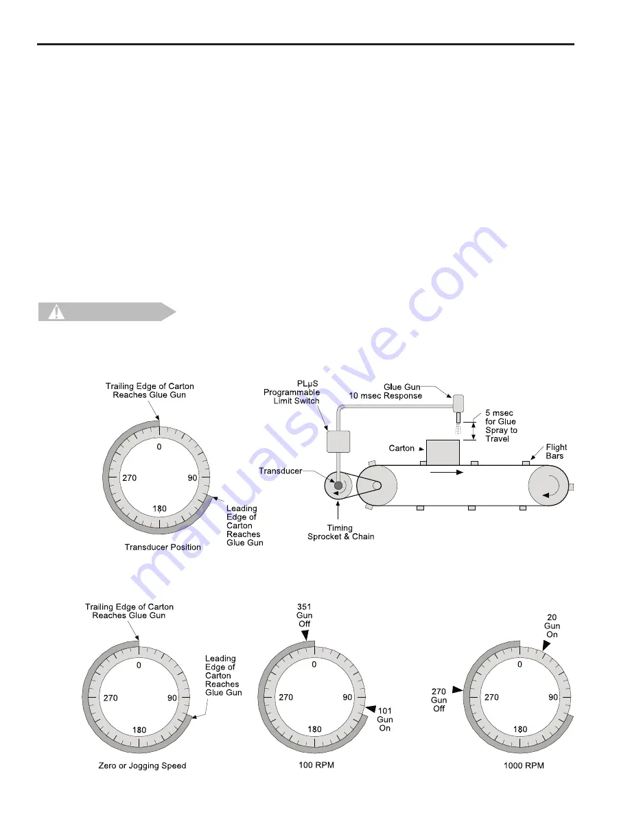
In the previous example, the gluing system requires 15 msec from the time the gun is
energized to the time the glue hits the carton. At 100 RPM, the transducer will rotate
0.6
°
/msec. Therefore, in the 15 msec response time, the transducer will rotate (15 msec
x 0.6
°
), or 9
°
. This means the glue gun must be energized at 101
°
, which is 9
°
before
the box arrives under the gun, and de-energized at 351
°
. At 1000 RPM, the transducer
will rotate (15 msec x 6
°
), or 90
°
during the response time, and the gun must be ener-
gized at 20
°
and de-energized at 270
°
. These values are visually represented in Figure
25 below.
Setting Speed Comp
In many applications, speed compensation can be set by jogging the line to determine
ON and OFF setpoints at zero speed, then entering the speed compensation value into
the controller. In the previous example, the line would be jogged until the leading edge
of the box reaches the gun at 110
°
of transducer rotation. The glue gun output would be
set to turn on at this point. Then, the line would be jogged until the trailing edge is under
the gun at 360
°
, and the glue gun output would be set to turn off.
Once these on and off setpoints are entered, the glue system response time of 15 msec
would be entered through SPEED COMP programming as described in Section 3. As
line speed increases, the PS-6244 will automatically advance the setpoints to maintain
the accuracy of the glue bead position.
When setting speed compensation on a system where zero speed setpoints have
been established, always adjust the speed compensation value. Do not adjust
the individual output setpoints!
Figure 24—Simple Application Using Speed Compensation
Figure 25—Speed Compensation at Various Speeds
C AU T I O N


