background image

USER MANUAL  ELDES ESIM252  V1.0                                     

27

XXXX_ 
SMSEXTRA: 
Z2:SS,SC, 
CC,SE,SD

FOR ADVANCED USERS

All these features can be configured using program “ELDES Configuration Tool“

3.9.2 Additional possibilities of controlling and configuring outputs C1 and C2

Normally C1 and C2 outputs can be controlled only by SMS message, as described in chapter 3.6, i. e. by enabling/disabling it for 

a permanent status or for a preset period. However, you can configure automatic enabling and disabling for a particular hour or 

control this function by a call.

3.9.2.1 Settings of an output controlled by calls

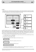
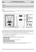
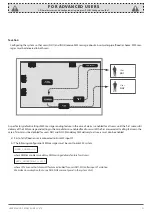
When calling on the number of system ESIM251 the call is rejected and no control operations are run. However, when a special mode 

is enabled C1/C2 outputs can be controlled by a call. It can be controlled by all users NO1-NO5, several users or only one of them.

By calling the system you can enable these 3 functions: enable/disable, enable/disable for a certain period or change output status 

with every call, i. e. one call enables the status, the next one disables it etc.

The parameters are changed by sending the following SMS message to the system Esim252:

XXXX – user password. COCx - output control by call; value can be COC1 (C1 output) or COC2 (C2 output). ValueN structure is CnVal, 

when Cn is command name ((2 letters), and Val-its value).

Value (CnVal) – table of values

Cn – command 

name (2 

letters)

Val – possible 

command 

meaning.

Command 

description

Initial factory 

default values

Comments

Enabling control 

via call

CE

1,2,3,4,5

Control via call mode 

is enabled for users 

No:1,2,3,4,5

E. g. CE25 means that users NO2 and NO5 will be 

able to control the output via call. 

CD

1,2,3,4,5

Control via call modes 

is disabled for users 

No:1,2,3,4,5

CD12345   

Disabled for all 

users NO1-NO5.

E. g. CD25 means that output control via call is 

disabled for users NO2 and NO5. 

Enabling/

disabling 

confirmation call 

(CallBack)

CS

1,2,3,4,5

Confirmation call 

mode is enabled for 

users No:1,2,3,4,5.

E. g. CS124 means that when users NO1, NO2 and 

NO4 control the output via call they will be notified 

about a successful output status change by a 

confirmation call.

CC

1,2,3,4,5

Confirmation call 

mode is disabled for 

users No:1,2,3,4,5.. 

CC12345

Disabled for all 

users NO1-NO5.

E. g. CC124 means that when users NO1, NO2 and 

NO4 control the output via call the call confirming 

about a successful output status change is disabled 

and users will not receive calls.

Confirmation 

call duration 

parameters

CT

1,2,3,4,5;1; s

Confirmation call 

is made for users 

No:1,2,3,4,5 when the 

ouput is turned on.

s- call time in seconds

СT112

СT212

СT312

СT412

СT512

The first number refers to user number. The second 

number is a command and the last number refers 

to call time in seconds.

E. g. СT412 means that if confirmation call mode 

is enabled, user NO4 will receive a call if he/she is 

trying to turn on the output.   

The system will call for 2 seconds.

1,2,3,4,5;0; s

Confirmation call 

is made for users 

No:1,2,3,4,5 when the 

output is turned off.

s- call time in seconds

СT108

СT208

СT308

СT408

СT508

The first number refers to user number. The second 

number is a command and the last number refers 

to call time in seconds. 

E. g. СT408 means that if confirmation call mode 

is enabled, user NO4 will receive a call if he/she is 

trying to turn off the output.

 The system will call for8 seconds.

Enabling/

disabling 

confirmation 

SMS 

(SMS confirm)

SS

1,2,3,4,5

Confirmation SMS 

mode is enabled for 

users No:1,2,3,4,5.

E. g. SS124 means that when users NO1, NO2 and 

NO4 control the output via call they will be notified 

about a successful output status change by a 

confirmation SMS message.

Before that the user has to turn on control from a 

particular number by using CE command.

SC

1,2,3,4,5

Confirmation SMS 

mode is disabled for 

users No:1,2,3,4,5.

SC12345 

Disabled for all 

users NO1-NO5.

E. g. SC124 means that when users NO1, NO2 and 

NO4 control the output via call the confirmation 

SMS message informing about the successful 

output status change is not sent.

XXXX_SMSEXTRA:COCx:Value1,Value2,……,ValueN

Summary of Contents for ESIM252

Page 1: ...GSM CONTROL SYSTEM ESIM252 ...

Page 2: ...ware personnel Mains power must be disconnected before any installation or tuning work starts The system installation or maintenance must not be done during stormy conditions The system must be powered by main 10 24V 50Hz 200mA AC or 10 24V 200mA DC power supply which must be approved by LST EN 60950 1 standard and be easily accessible nearby the device When connecting the power supply to the syst...

Page 3: ...is very important to read User Manual before start using the system A quick start guide is located in first two chapters Chapter 3 and 4 describe additional system capa bilities CONTENT 1 General Information 1 1 Function 4 1 2 Operation Description 4 1 3 Technical Specifications 5 1 4 Connector Functionality 5 1 5 Connection Circuit 6 1 6 System Installation 7 2 System Pre operation and the Main C...

Page 4: ... switched Ways of initiating an event Event when an input is violated Alarm Phone call initiated and or SMS is delivered to user s when the signal is transmitted to an input Event when a zone is restored Restore Phone call initiated and or SMS is delivered to user s when the previously transmitted input signal disappears Impulse counting Input is considered as violated only if the number of the pr...

Page 5: ...0Hz 0 5A Dimensions 82x63x20mm Operating temperature range 20 55o C 30 55o C with limitations 1 4 Connector Functionality ANT GSM MODEM SIM CARD MIC LED1 LED2 DEFAULT D1 D2 AC DC F1 RELAY1 RELAY2 COM Z5 Z4 Z3 Z2 Z1 USB Short explanation of the main units GSM MODEM GSM network 850 900 1800 1900 MHz modem SIM CARD SIM card LED Light emitting diodes indicator DEFAULT Connectors D1 and D2 for restorin...

Page 6: ... also possible to connect Z1 Z3 Z4 Z5 inputs to for instance motion sensor or any other sensor as well as automatics device provided the inputs are commuted with COM Input Z2 is commuted with a high level impulse Impulse duration is 600ms Picture 2 Picture3 AC power supply connection circuit AUX AUX HIGH LEVEL Z1 Z2 Z3 Z4 Z5 COM RELAY1 RELAY2 AC DC PGM1 PGM3 PGM4 PGM5 PGM2 GSM Control System ESIM2...

Page 7: ...ection of input output connectors use 0 50 mm2 1 thread cable 1 Fasten the system in the box using fastening holders 2 Place SIM card in the holder but make sure that SIM card PIN code is disabled PIN code can be disabled by putting SIM card into mobile phone and following proper menus SIM card should not have any remaining SMS messages 3 Connect the circuit as shown in fig No 2 Power supply cable...

Page 8: ...ould get an SMS message asking to change default password Otherwise check for network connection and change SMS central number SMS central number is saved in SIM card therefore if SIM card has been used to send SMS messages with a mobile phone then you don t need to change SMS central number Often SMS central number is already saved in SIM card by cellular operator Central number can be entered by...

Page 9: ... described above New number will overwrite old one the refore no erasing is necessary 2 3 2 Verification of Saved Numbers To inquire the system about pre programmed numbers send the following SMS message The system will reply with all pre programmed numbers 2 3 3 Deletion of Saved Numbers To erase NR2 NR5 send the following SMS message E g XXXX_NR3 DEL The system will not allow erasing first numbe...

Page 10: ...nd Texts cannot be the same as configuration and control com mands such as ON OFF STATUS etc Input restore text If you want to be notified by an SMS message when a violated zone is restored Restore mode must be turned on The mode is turned on by sending a particular SMS command Please refer to chapter 3 9 or configuration program Input restore text is changed by sending the following SMS mesaage O...

Page 11: ...onfigured by sending the following SMS message PP message period in days valid values 00 10 VV time when message is sent valid values 00 23 E g XXXX_INFO 01 10 means that status message will be sent every 1 day at 10 00 If PP value is 0 andVV in the range of 1 23 then periodic status messages will be sent multiple times per day with period being specified as VV time E g XXXX_INFO 0 2 means that st...

Page 12: ...e E g XXXX_PUMP ON Timer GSM control system ESIM252 has internal timer This feature allows any output to be turned on or off for a specified time period The following SMS command should be sent x output number possible values 1 C1 or 2 C2 ON output enabled OFF disabled vv hours valid values 00 23 mm minutes valid values 00 59 ss seconds valid values 00 59 It is not allowed to have all values equal...

Page 13: ...etwork coverage or was engaged To turn on this feature send the following SMS message ATTENTION When this feature is enabled it will not be possible to stop calling the next user in the sequence even if the call is answered To disable this function send the following SMS message If you want to configure calling only to particular users or only for particular zones refer to chapter 3 9 or use confi...

Page 14: ...ault settings calling feature in the case of alarm is also enabled for all users therefore call function must be disabled for all users except user NO2 a First of all alarm system unit must be programmed in the way so that when security is armed in office A output PGM1 is turned on and when security is armed in office B output PGM2 is turned on b Output PGM1 is connected to ESIM252 input Z1 and ou...

Page 15: ...erefore call function must be disabled for all users except user NO3 SMS message sending feature must also be enabled for user NO3 when input Z3 is restored a First of all alarm system unit must be programmed in the way so that when PIR movement sensor s input is violated output PGM3 is activated b Output PGM3 is connected to ESIM252 input Z3 c The following configuration SMS message must be sent ...

Page 16: ...arm messages Besides as per factory default settings calling feature in the case of alarm is also enabled for all users therefore call function must be disabled for all users except users NO3 and NO4 As per factory default settings in the case of alarm the system rings until the first answered call therefore in this case nothing should be configured a First of all alarm system unit must be program...

Page 17: ... call function must be disabled for users NO1 NO2 and NO4 and left enabled for users NO3 and NO5 Also it is necessary to enable mandatory calling feature for all preset users see more in chapter 3 8 a First of all alarm system unit must be programmed in the way so that when security sensors are violated the signal must be transmitted to alarm system unit s output PGM5 b Output PGM5 is connected to...

Page 18: ... be programmed in the way so that when security sensors are violated the signal must be transmitted to alarm system system unit output PGM b Output PGM is connected to ESIM252 input Z1 c The following two configuration SMS messages must be sent to Esim252 system where SMSALL enables mandatory SMS message delivery for all users Where SC345 means that alarm SMS message sending is disabled for users ...

Page 19: ... change by SMS message MS10 means that the output is activated when user NO1 calls the system MS30 means that the output is activated when user NO3 calls the system MS40 means that the output is activated when user NO4 calls the system MS50 means that the output is activated when user NO5 calls the system MS1T0 0 1 means that output status is changed for 1 second when user NO1 calls the system MS3...

Page 20: ...put was turned off a First of all ESIM252 system output C1 has to be connected to the connectors of heating controller unit b The following configuration SMS message must be sent to Esim252 system where COC1 means C1 output control by call is enabled for users NO1 CS1 means that confirmation call feature is enabled for user NO1 after output C1 status changes CT113 means that user NO1 will receive ...

Page 21: ...rs must also be enabled a First of all a flood sensor is connected to Esim252 input Z1 b The following configuration SMS messages must be sent to Esim252 system where SMSALL enables mandatory SMS message delivery feature for all users where CC12 means that alarm call feature is disabled for users NO1 NO2 after input Z1 violation We make an assumption that users NO3 NO5 were not preset in the syste...

Page 22: ...e signal disappears a First of all a signal indicating gas boiler breakdown isconnected to Esim252 input Z1 b The following configuration SMS message must be sent to Esim252 system where SC23 means that alarm SMS message sending is disabled for users NO2 NO3 input Z1 is violated CC123 means that alarm calls are disabled for users NO1 NO2 and NO3 after input Z1 is violated We make an assumption tha...

Page 23: ...m252 input Z3 b The following configuration SMS message must be sent to Esim252 system where SC13 means that alarm SMS message sending is disabled for users NO1 NO3 after input Z3 zone violation CC123 means that alarm calls are disabled for users NO1 NO2 and NO3 after input Z3 violation We make an assumption that users NO4 NO5 were not entered to the system at all IE1 enables impulse counting mode...

Page 24: ...ssage must be sent to Esim252 system MS10 means that the output is activated when user NO1 calls the system MS20 means that the output is activated when user NO2 calls the system MS30 means that the output is activated when user NO3 calls the system MS1T0 0 2 means that output status is changed for 2 seconds when user NO1 calls the system MS2T0 0 2 means that output status is changed for 2 seconds...

Page 25: ...etting input type 0 NO normally open LI0 Normally open Possibility to change input type i e to invert E g LI0 It means that the input is considered inactivated if there is no signal 1 Setting input type 1 NC normally closed Possibility to change input type i e to invert E g LI1 means that input is in normal status when the signal is transmitted The event appears only when the signal disappears Imp...

Page 26: ...e only user NO4 is called LE1 means that input type for input Z1 will be inverted i e the previous NO is changed to NC normally closed This means that the input is violated only when the signal disappears and the input is restored only in case when the signal appears DV900 means that input Z1 is violated only if the signal is suspended at least for 900ms Please note that input type was inverted to...

Page 27: ...for users No 1 2 3 4 5 E g CS124 means that when users NO1 NO2 and NO4 control the output via call they will be notified about a successful output status change by a confirmation call CC 1 2 3 4 5 Confirmation call mode is disabled for users No 1 2 3 4 5 CC12345 Disabled for all users NO1 NO5 E g CC124 means that when users NO1 NO2 and NO4 control the output via call the call confirming about a su...

Page 28: ...he enables C1 input but cannot disable it via call The user can disable it via SMS message if he she knows the password MS42 means that when user NO4 calls the system he she will either enable or disable output C1 TOGGLE mode is on It depends on the output status before making a call MS1T0 0 40meansthatwhenuserNO1makeacalltothesystem theoutputisturnedonfor40secondsandthenitautomaticallyturnsoff To...

Page 29: ... enabled the call will be forwarded to the user who is trying to turn off the output The system will call for 8 seconds Enabling disabling confirmation SMS message SMS confirm SB 1 Confirmation SMS mode is enabled for all users SB1 Enabled for all users NO1 NO5 SB1 means that when all users control the output via SMS message they will be informed about a successful output status change by a confir...

Page 30: ...utes for which output status is changed E g PT1 20 means that after automatic enabling disabling which is indicated in WT command relay status is changed to opposite for 1 hour and 20 minutes Setting confirmation call for period start CS 1 Users are notified about period start by a confirmation call CS1 means that the preset user is informed about the period start of output turning on or off via s...

Page 31: ...t output turning off by SMS message 0 Users are not notified about period end by SMS message SE0 SE0 means that nobody is informed about period end by SMS message Example of output C1 configuration for a schedule This message configures C1 output parameters using a schedule WT20 15 means that output turning on time is set for 20 15 every day ST1 means the user set the output to turn on on that tim...

Page 32: ...ternal power supply circuit not properly connected blown fuse no network signal Indicator blinking several times per second SIM card is not inserted PIN code hasn t been disabled Sim card not active System does not send any SMS messages and or does not ring SIM card account depleted incorrect SIM central number no network signal user number is not programmed or disabled access from unknown numbers...

Page 33: ...USER MANUAL ELDES ESIM252 V1 0 33 ...

Page 34: ...34 For notes ...

Page 35: ...USER MANUAL ELDES ESIM252 V1 0 35 For notes ...

Page 36: ...Made in Lithuania www eldes lt ...

Reviews: