KGL Operating Manual – VS 3010 BS
2018-07-02
/
90 178
After changing the switch positions of both S1 and S2 (address selector switch for CAN bus), the
controller
be disconnected from the power supply for a short time so that the new settings will
must
be adopted!
5.2.3 Setting the CAN bus address with S2
Setting of the CAN bus address (node number) / deactivating CAN bus communication
he decade switch S2 specifies the CAN bus address or node number (Node Nr.) The setting is generally made
at the manufacturer of the switchgear.
S2 decade switch
Switch position
CAN bus address
/ node number
(Node Nr.)
Function
0
NONE
CAN bus communication of the pack controller disabled
1..9
101..109
Node number nnn is assigned to the pack controller
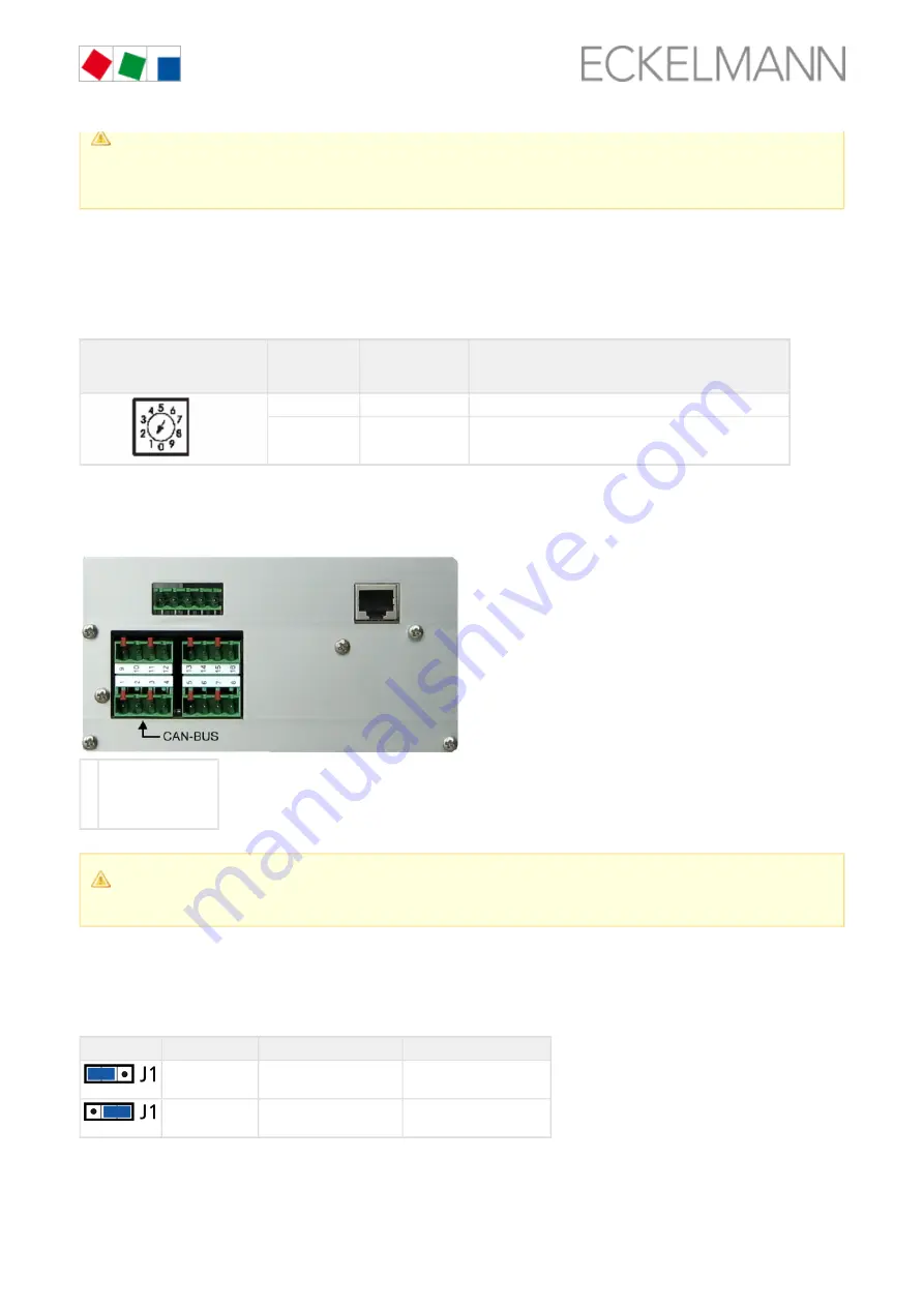
Connection to the CAN bus
The connection to the CAN bus is made using the terminals 1-4 installed on the left side, see chapter
.
bus, SIOX and Modbus (ebmpapst fans terminal assignment), page 114
1
2
3
4
SHIELD
GROUND - green
- brown
CAN-LOW
CAN-HIGH - white
After changing the switch positions of both S1 and S2, the
be disconnected from the
controller
must
power supply for a short time so that the new settings will be adopted!
5.2.4 Setting of the interface RS485/TTY using jumper J1
Setting of the interface
The jumper J1 specifies the function of the interface.
Jumper J1
Jumper position
Interface
Function
Left
RS485 active
(terminals 13/14/15/16)
Factory setting,
currently has no function
Right
TTY active
(terminals 9/10/11/12)
currently has no function
For details, see chapter
CAN bus, SIOX and Modbus (ebmpapst fans) terminal assignment, page 114
5.2.5 Configuration of the analogue inputs and outputs at the factory


