EBARA GP Operating And Maintenance Manual Download Page 29


ENGLISH 

maintenance  manual,  adding  the  values  indicated  in  the 
following table (applicable for 50 and 60Hz): 

By  sound  pressure  level  is  meant  the  mean  value  of  the 
measurements taken at a distance of 1 m from the set in a free 
field. For the noise value tolerance, refer to the manual of the 
single main electric pump, as it is the main source of noise. 
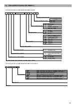
Standard set 

Configured 

set 

L

pA


dB

(

A

)


L

WA


dB

(

A

)


1GP/1GPE/2GPS/2GPES 

13 

2GP/2GPE/3GPS/3GPES 

2-pump sets 

15 

2GPJ/2GPEJ 

16 

3GP/3GPE/4GPS/4GPES 

3-pump sets 

17 

3GPJ/3GPEJ 

6,5 

17,5 

4GP/4GPE 

4-pump sets 

18 

4GPJ/4GPEJ 

7,5 

18,5 

6.4.  TESTING 

100%  of  the  pressure  booster  sets  are  subjected  to  routine 
hydraulic,  mechanical  and  electrical  tests  before  being 
packaged.  In  particular,  the  operation  of  the  set  and  each 
individual  pump  is  checked,  a  seal  test  is  performed  with  the 
delivery outlet closed and the rated head is checked. 

7. 

HANDLING AND STORAGE 

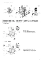
7.1.  HANDLING (see the attached diagrams fig. B) 


Observe  the  current  accident  prevention 
regulations. 
Possible risk of crushing.  
Use safety footwear. 

ATTENTION 

Only  use  the  procedures  specified  below  and 
the  lifting  points  provided  for  handling  the 
package  and  the  set  after  the  packaging  has 
been removed. 

The  pressure  booster  sets  are  sent  packaged  on  wooden 
pallets and in a cardboard box for smaller sizes; in the case of 
larger sets, in addition to the pallet also a wooden crate is used 
and additionally covered with nylon film. In the case of obvious 
dimensional  problems,  the  intake  manifold  can  be  supplied 
disassembled.  Various  packaging  systems  (by  sea  or  other) 
will be used based on specific customer request. 
 
The  set  must  be  handled  with  utmost  caution  during  handling 
and  transport.  Particular  attention  must  be  paid  when  lifting 
and putting down the set: 

  when the set is on a pallet, move it using a lifting carriage. 

Pay attention to the weight indicated directly on the pallet. 
Check  the  stability  of  the  pallet  on  the  lifting  carriage 
before performing lifting or moving operations; 

  after  the  pallet  and  packaging  have  been  removed,  only 

use  the  specific  hooking  points  provided  on  the  base  for 
movement  (note:  to  lift  the  set  off  the  pallet,  remove  the 
fastening  screws  that  anchor  the  set  to  the  pallet  itself). 
For  larger  sets,  there  are  4  eyebolts  on  the  base.  For 
smaller sets, there are 4 holes on the base for lifting using 
pipes  (not  supplied  with  the  set).  It  is  recommended  to 
use  pipes  with  a  section  suitable  for  lifting  and  to  pay 
attention when fastening the lifting belts to prevent the set 
from falling. For their movement, take the weight indicated 
on  the  pallet  into  account.  Do  not  anchor  on  pumps, 
motors,  manifolds  or  other  accessories.  Make  sure  that 
the  set  is  firmly  fixed  to  the  provided  lifting  points  before 
performing the lifting and moving operations. 

Blows,  falls  or  swinging  must  be  avoided,  which  could  cause 
non apparent damage. Do  not stand  near the set while lifting, 
handling or setting it down. 

7.2.  STORAGE 

To maintain the full efficiency of the set: 

  store the product in a covered and dry location away from 

heat  sources  and  protected  against  impacts,  dirt  and 
vibrations; 

  do not place heavy objects on the packaging; 

  store  the  product  at  an  ambient  temperature  between 

+5°C and +40°C (41°F and 104°F) with a relative humidity 
of 60%. 

8. 

INSTALLATION 


Installation  must  be  performed  by  specialised 
and qualified personnel (refer to the definition of 
qualified  personnel  in  the  INTRODUCTION 
chapter). 

8.1.  MECHANICAL FASTENING (see the attached 

diagrams fig. C) 

  The set must be positioned on a flat surface (refer also to 

the  TECHNICAL  CONSTRUCTION  CHARACTERISTICS 
chapter for the characteristics required for the installation 
environment). 

  The  set  must  be  positioned  in  a  protected  area  with 

reserved  access  where  there  is  sufficient  space  for 
maintenance and removal. It is recommended to maintain 
at least three sides free, i.e. the side of the electric control 
panel  or  protection  panel  (minimum  100  cm  of  free 
space),  the  side  opposite  of  the  panel  and  the  side  with 
the connections to the delivery and intake lines (minimum 
50 cm of free space). 

  If the set is provided with feet, the set must be placed on 

the ground. 


The set arrives with the feet disassembled. The 
feet  must  be  assembled  with  the  set  lifted  off 
the  ground.  Therefore  pay  utmost  attention 
during  this  operation  to  keep  the  set  from 
falling. 
Use appropriate PPE. 

  If the set does not have feet, it can be fixed to the ground 

by means of anchors using the provided holes. 

8.2.  CONNECTION TO THE HYDRAULIC SYSTEM (see 

the attached diagrams fig. D) 

Refer to the images to identify the referenced points (“a”,”b”…). 


The  pipes  must  be  sized  to  support  the 
maximum  operating  pressure  of  the  set 
(CHECK  THE  PUMP  PRESSURE  ON  THE 
PUMP 

PLATE 

TO 

DETERMINE 

THE 

MAXIMUM  PRESSURE  AT  WHICH  THE  SET 
CAN OPERATE) 


  If  the  set  arrives  with  the  intake  manifold  disassembled, 

make the connection using a pipe union or counter flange. 


Connect  the  set's  intake  (“a”)  and  delivery  (“b”)  lines  to 
the system. The unit is supplied with threaded flanges or 
flanged connections and with closing caps/flanges for the 
manifold side not used for the connection. The dimension 
of the connection pipes must be  equal to or greater than 
the  set's  intake  and  delivery  manifolds;  they  must  be  as 
short and straight as possible, and with a path that always 
ascends towards the pumps (intake), using as few elbows 
as  possible,  avoiding  minimum  number  of  elbows, 
avoiding  goosenecks  that  could  cause  siphons  or  air 
pockets.  Please  note  that  in  sets  with  1  pump,  the 
manifold  is  not  present  and  the  connection  is  made 

Summary of Contents for GP

Page 1: ...TIONS D ORIGINE FR DRUCKERH HUNGSANLAGEN Gebrauchs und Wartungshandbuch BERSETZUNG AUS DEN URSPR NGLICHEN ANWEISUNGEN DE GRUPOS DE PRESURIZACI N Manual de instrucciones de uso y mantenimiento TRADUCCI...

Page 2: ......

Page 3: ...to e o esperienza tecnica rilevanti sull argomento che gli permettono di percepire i rischi e di evitare i pericoli che si presentano durante l uso di un prodotto al personale addetto al funzionamento...

Page 4: ...tto tensione pu provocare gravi incidenti anche mortali alle persone Verificare prima di avviare l impianto che tutti i dispositivi e componenti elettrici cavi compresi siano efficienti Nell avviare i...

Page 5: ...ati con le seguenti tipologie di pompe AGA CDX 2CDX 2CD CDA CMA CMB COMPACT CVM EVM EVML EVMG EVMS EVMSL EVMSG GS JE JEX MATRIX MD MMD MULTIGO 3M 3LM 3S 3LS 3D 3DS 3P 3LP 3DP 5 2 COMPONENTISTICA I com...

Page 6: ...lizzando il carrello di sollevamento Prestare attenzione al peso indicato sul pallet stesso Accertare la stabilit del pallet sul carrello di sollevamento prima di effettuare le operazioni di sollevame...

Page 7: ...sopra battente Per necessit di prova del gruppo aggiungere a valle un T con valvola d intercettazione e relativa tubazione di ricircolo verso il serbatoio di aspirazione o a perdere 8 3 COLLEGAMENTO...

Page 8: ...re fino al trabocco Richiudere poi con il relativo tappo 9 COLLEGAMENTO ELETTRICO Il collegamento elettrico deve essere effettuato da personale qualificato fare riferimento alla definizione di persona...

Page 9: ...rica I gruppi di pressurizzazione non richiedono particolare manutenzione Gli interventi da effettuare vengono divisi in interventi di manutenzione ordinaria o straordinaria a seconda delle competenze...

Page 10: ...troppo elevata Regolare pressione di lavoro a valori conformi alla conformazione impianto caratteristiche pompa Senso di rotazione errato prestazioni ridotte Controllare senso di rotazione Pompe trif...

Page 11: ...se necessario RIAVVI POMPA E TROPPO FREQUENTI Errato settaggio dei parametri di pressione di set e pressione di riavvio Verificare e correggere settaggio parametri vedi manuale quadro Errato settaggio...

Page 12: ...iudere lentamente la valvola di intercettazione a valle del gruppo fino alla pressione di arresto voluta lettura sul manometro regolare il pressostato n 1 mediante la rotazione del dado o della vite A...

Page 13: ...aspirazione per i gruppi ad 1 pompa 6 collettore in mandata o attacco mandata per i gruppi a 1 pompa 7 valvole di intercettazione in aspirazione e mandata 8 valvola di ritegno 9 nipples in aspirazione...

Page 14: ...evamento pallet tramite carrello di sollevamento 2 Sollevamento tramite tubi 3 Sollevamento tramite golfari C FISSAGGIO MECCANICO 1 Fissaggio piedini su basamento 2 Punti di fissaggio per ancoraggio a...

Page 15: ...angiata 2 Gruppo tipo con collegamenti flangiati b Linea di mandata 3 Gruppo tipo ad 1 pompa c Tronchetto da G1 E ADESCAMENTO F AVVIO DELL IMPIANTO g Tappo di carico h Valvole di intercettazione in ma...

Page 16: ...del quadro alla linea di alimentazione vedere manuale del quadro di comando allegato i collegamenti tratteggiati sono competenza dell installatore VERSIONE CON INVERTER A BORDO MOTORE VASCO QP Quadre...

Page 17: ...i collegamenti tratteggiati sono competenza dell installatore Nota applicazione ferrite Lm modelli E SPD MT 2200 Per i modelli monofase E SPD MT 2200 la ferrite posizionata in prossimit dell inverter...

Page 18: ...e vedere manuale del quadretto allegato i collegamenti tratteggiati sono competenza dell installatore Nota applicazione ferrite A B e C modelli E SPD TT11000 Per i modelli trifase E SPD TT11000 devono...

Page 19: ...OTORI MONOFASE COLLEGAMENTO MOTORI TRIFASE CON QUADRO DI COMANDO EP EP E SP EFC SP MFC COLLEGAMENTO TRIANGOLO Con alimentazione trifase EP E 5 5 kW EFC T 5 5 kW MFC 5 5 kW COLLEGAMENTO STELLA Con alim...

Page 20: ...ENTO MOTORI TRIFASE CON INVERTER A BORDO MOTORE VASCO E SPD COLLEGAMENTO TRIANGOLO Con alimentazione monofase VASCO da 1 5 a 3 kW E SPD 2 2 kW Con alimentazione trifase VASCO da 5 5 a 45 kW COLLEGAMEN...

Page 21: ...20 COLLEGAMENTO A QUADRO DI PROTEZIONE INVERTER A BORDO MOTORE VASCO E SPD H PRESSOSTATO DI AVVIAMENTO POMPA...

Page 22: ...lvolame in ottone Coll zincato AISI 304 J S Quadro di comando EP EP E E SPD MT Con pompa pilota Dimensionato con pompa e in standby VASCO MT VASCO TT Velocit fissa E SPD TT TYPE KEY GRUPPI DI PRESSURI...

Page 23: ...SURIZZAZIONE SERIE GP GPE GPS GPES GPJ GPEJ 1 TYPE Type key 2 P N Codice articolo 3 S N Numero di serie GRUPPI DI PRESSURIZZAZIONE CONFIGURATI 1 TYPE Type key 2 I C Codice identificativo 3 P N Codice...

Page 24: ...itivi in carta 3 Foglio o sacchetto in plastica Plastica 4 Maniglia 5 Film estensibile 6 Pluriball 7 Reggia Indifferenziata o consulta le indicazioni del tuo comune 8 Inserto polistirolo 9 Riempitivi...

Page 25: ...RA PUMPS EUROPE S p A con sede in Via Campo Sportivo 30 38023 Cles TN ITALY dichiariamo sotto la nostra responsabilit che i nostri Gruppi di pressurizzazione sono in conformit alle disposizioni delle...

Page 26: ...ing and or technical experience that is relevant to the argument that permit them to understand the risks and avoid hazards that occur while using a product personnel assigned to operating the set per...

Page 27: ...The device is not intended to be used by people children included with reduced physical sensory or mental capabilities or lack of experience and knowledge unless they have been given instruction conce...

Page 28: ...ms The treated liquid must be potable clean water rainwater or groundwater or a mixture free of solid or fibre bodies in suspension free of aggressive chemical substances at a temperature compatible w...

Page 29: ...re that the set is firmly fixed to the provided lifting points before performing the lifting and moving operations Blows falls or swinging must be avoided which could cause non apparent damage Do not...

Page 30: ...WITH MEMBRANE PRESSURE TANK For correct operation of the pressurization system we recommend the use small size pressure tank It is necessary to stabilize any pressure fluctuations during the variatio...

Page 31: ...t the auxiliaries operate with very low voltage are easy to replace and find commercially For connecting the set to the electrical mains refer to the attached manuals and the instructions provided on...

Page 32: ...o not leak while the system is operating Check that the system isolating and stop valves are not clogged If necessary restore the line to its original state EVERY 6 MONTHS 11 2 EXTRAORDINARY MAINTENAN...

Page 33: ...rn valves and replace if necessary TOO FREQUENT PUMP RESTARTS Incorrect setting of set pressure and restart pressure parameters Check and set proper parameters see the control panel user manual Incorr...

Page 34: ...tion will start the pump Check the adjustment by increasing and decreasing the pressure downstream of the system always using the isolating valve perform the same operations for the set s remaining pr...

Page 35: ...ntake manifold or intake connection for sets with 1 pump 6 delivery manifold or delivery connection for sets with 1 pump 7 intake and delivery isolating valves 8 stop valve 9 intake nipples with G 1 2...

Page 36: ...B LIFTING 1 Pallet lifting with the lifting carriage 2 Lifting with pipes 3 Lifting with eyebolts C MECHANICAL FASTENING 1 Feet fastening on the base 2 Fastening points for anchoring to the ground usi...

Page 37: ...ers optional for flanged pump suction line 2 Group with flanged connections b Delivery line 3 Group with 1 pump c G1 pipe section E PRIMING F STARTING THE SYSTEM g Filling cap h Delivery isolating val...

Page 38: ...e panel to the power supply line see the attached control panel manual The connections with dash lines are the responsibility of the installer VERSION WITH ON BOARD PUMP INVERTER VASCO QP Protection p...

Page 39: ...with dash lines are the responsibility of the installer Note Lm magnetic core application E SPD MV model MT2200 For single phase models E SPD MV 2200 the magnetic core is positioned close to the inve...

Page 40: ...al The connections with dash lines are the responsibility of the installer Note Magnetic core application A B C E SPD model TT11000 For E SPD model TT11000 is necessary to install three magnetic cores...

Page 41: ...CONNECTION With three phase power supply EP E 5 5 kW EFC T 5 5 kW MFC 5 5 kW STAR CONNECTION With three phase power supply EP E 4 kW EFC T 4 kW MFC 4 kW YELLOW GREEN PANEL PANEL MOTOR PROTECTOR IN TER...

Page 42: ...CONNECTION With single phase power supply VASCO from 1 5 to 3 kW E SPD 2 2 kW With three phase power supply VASCO from 5 5 to 45 kW STAR CONNECTION With three phase power supply VASCO 4 kW E SPD 4 kW...

Page 43: ...19 ENGLISH PROTECTION PANEL CONNECTION WITH ON BOARD PUMP INVERTER VASCO E SPD H PUMP STARTING PRESSURE SWITCH...

Page 44: ...nifold J XXX VASCO TT S EP EP E control panel E SPD MT With pilot pump Dimensioned with pump s in stand by Multi Inverter SP MFC 316 H 3 GPE MATRIX 5 6 1 3I MFC S J CONFIGURED PRESSURE BOOSTER SET TYP...

Page 45: ...STANDARD PRESSURE BOOSTER SETS GP GPE GPS GPES GPJ GPEJ 1 TYPE Type key 2 P N Part number 3 S N Serial number CONFIGURED PRESSURE BOOSTER SETS 1 TYPE Type key 2 I C Identification code 3 P N Part num...

Page 46: ...ion 1 Box Paper 2 Paper filler 3 Plastic sheet or bag Plastic 4 Handle 5 Stretch film 6 Bubble wrap 7 Strap Undifferentiated or check the instructions of your municipality 8 Polystyrene insert 9 Foam...

Page 47: ...l We EBARA PUMPS EUROPE S p A headquartered in Via Campo Sportivo 30 38023 Cles TN ITALY declare under our own responsibility that our Pressure booster sets comply with the provisions of the following...

Page 48: ...24 ENGLISH 18 UKCA DECLARATION OF CONFORMITY...

Page 49: ...permettent de percevoir les risque et d viter les dangers qui se pr sentent pendant l utilisation d un produit au personnel charg du fonctionnement du groupe du personnel charg de faire fonctionner ne...

Page 50: ...n effectu e sur le groupe et sur ses parties avec l installation lectrique sous tension peut provoquer de graves accidents aux personnes voire la mort V rifier avant de mettre en marche l installation...

Page 51: ...pr sent manuel Remarque dans les groupes avec un dispositif de commande VASCO et E SPD il est possible d identifier une pompe MA TRE la premi re pompe gauche en regardant le groupe du c t panneaux don...

Page 52: ...es groupes d une certaine dimension en plus de la palette on utilise une cage en bois avec une protection suppl mentaire de film en nylon Pour des probl mes d encombrement vidents le collecteur d aspi...

Page 53: ...s brides de support sont pr sentes sur le collecteur les utiliser pour fixer le collecteur une structure de fa on r duire la charge sur les pompes Il est appropri d installer imm diatement en aval du...

Page 54: ...de la pompe dans le cas d une charge positive il est conseill que celle ci ne d passe pas 5 m de colonne d eau Cependant il ne peut pas tre utilis en combinaison avec des pompes submersibles o il n e...

Page 55: ...muter le fonctionnement du groupe en mode automatique Pour la proc dure suivre voir le manuel du tableau lectrique en annexe ouvrir lentement la vanne d arr t en aval de l installation Le groupe se me...

Page 56: ...ntensit s voir les donn es du moteur et le manuel d utilisation du coffret de commande Activation de la commande externe par exemple interrupteur flotteur manque d eau V rifiez la pr sence de l eau et...

Page 57: ...glage correct des pressostats Absence ou Installez un r cipient pr chargement dimensionnement incorrect du r servoir vessie sous pression de taille ad quate s il n y en a pas et ou v rifiez que la pr...

Page 58: ...tallation toujours l aide de la vanne d arr t r aliser les m mes op rations pour le reste de pressostats du groupe Utiliser pour le r glage de mise en marche et d arr t des pompes les indications du t...

Page 59: ...l aspiration pour les groupes avec 1 pompe 6 collecteur de refoulement ou fixation du refoulement pour les groupes avec 1 pompe 7 vannes d arr t l aspiration et au refoulement 8 vanne de retenue 9 nip...

Page 60: ...de la palette au moyen de chariot l vateur 2 Levage au moyen de tuyaux 3 Levage au moyen d anneaux de levage C FIXATION M CANIQUE 1 Fixation des pieds sur le b ti 2 Points de fixation pour la fixation...

Page 61: ...aspiration de la pompe bride 2 Groupe type avec raccordements brid s b Ligne de refoulement 3 Groupe type 1 pompe c Tron on de G1 E RACCORDEMENT F MISE EN MARCHE DE L INSTALLATION g Bouchon de remplis...

Page 62: ...la ligne d alimentation voir le manuel du panneau de commande en annexe Les branchements en pointill sont la charge de l installateur VERSION AVEC ONDULEUR BORD DE LA POMPE VASCO QP Tableau de protec...

Page 63: ...u tableau en annexe Les branchements en pointill sont la charge de l installateur Note application ferrite Lm mod les E SPD MT2200 Pour les mod les monophas s E SPD MT2200 la ferrite est plac e proxim...

Page 64: ...leau en annexe Les branchements en pointill sont la charge de l installateur Note d application ferrite A B C mod les E SPD TT11000 Pour les mod les triphas s E SPD TT11000 trois ferrites doivent tre...

Page 65: ...MENT TRIANGLE Avec alimentation triphas e EP E 5 5 kW EFC T 5 5 kW MFC 5 5 kW BRANCHEMENT TOILE Avec alimentation triphas e EP E 4 kW EFC T 4 kW MFC 4 kW JAUNE VERT PANNEAU PANNEAU PROTECTION MOTEUR D...

Page 66: ...NCHEMENT TRIANGLE Avec alimentation monophas e VASCO de 1 5 kW 3 kW E SPD 2 2 kW Avec alimentation triphas e VASCO de 5 5 kW 45 kW BRANCHEMENT TOILE Avec alimentation triphas e VASCO 4 kW E SPD 4 kW U...

Page 67: ...FRAN AIS 20 BRANCHEMENT AU PANNEAU DE PROTECTION ONDULEUR SUR LE MOTEUR VASCO E SPD H PRESSOSTAT DE MISE EN MARCHE DE LA POMPE ENTR E DE PUISSANCE 1 230V 10 ENTR E DE PUISSANCE 3 400V 10...

Page 68: ...ltiple SP MFC Hydraulique Complet Hydraulique b ti Vannes en laiton AISI 304 Coll galvanis vann Laiton J S Panneau de commande EP EP E E SPD MT 304 H 3 GPE MATRIX 5 6 1 3I MFC S J TYPE KEY GROUPES DE...

Page 69: ...OUPES DE SURPRESSION S RIE GP GPE GPS GPES GPJ GPEJ 1 TYPE Type key 2 P N Code de l article 3 S N Num ro de s rie GROUPES DE SURPRESSION CONFIGUR S 1 TYPE Type key 2 I C Code d identification 3 P N Co...

Page 70: ...Feuille ou sac en plastique Plastique 4 Manche 5 Film tirable 6 Film bulles 7 Bande de fixation Indiff renci ou consultez les indications de votre commune 8 Insert en polystyr ne 9 Remplisseurs de mou...

Page 71: ...PUMPS EUROPE S p A dont le si ge se trouve Via Campo Sportivo 30 38023 Cles TN ITALIE d clarons sous notre responsabilit que nos Groupes de surpression sont conformes aux dispositions des directives...

Page 72: ...N 82079 1 handelt es sich bei qualifiziertem Personal um Personen mit Ausbildung Schulung und oder technischer Erfahrung im das f r den Betrieb der Anlage zust ndige Personal mit der korrekten Funktio...

Page 73: ...rrichtungen die f r die verschiedenen Operationen der Anlage n tig sind und im vorliegenden Handbuch und in den beiliegenden Dokumenten zu den Komponenten der Anlage aufgef hrt werden Trennen Sie vor...

Page 74: ...Pumpen bei der ersten Pumpe mit ver nderlicher Drehzahl und bei den anderen in Kaskadenschaltung mit fester Drehzahl Schalttafel SP MFC f r den Betrieb von dreiphasigen Pumpen mit ver nderlicher Drehz...

Page 75: ...der F rderh he des Typenschilds durchgef hrt 7 F RDERUNG UND LAGERUNG 7 1 F RDERUNG siehe beiliegende Abbildungen Abb B Beachten Sie die geltenden Unfallverh tungsvorschriften M gliche Quetschgefahr B...

Page 76: ...saugung und m glichst wenige Kurven aufweisen damit Windungen vermieden werden die Siphons oder Lufts cke verursachen k nnen Bitte beachten Sie dass bei Anlagen mit 1 Pumpe kein Sammelrohr vorhanden i...

Page 77: ...in auch nicht an den Ausg ngen der Einzelpumpen sondern nur auf der Saugseite Die automatische Luftzufuhr eignet sich f r Anlagen bei denen ein regelm iger Betrieb der Elektropumpen erforderlich ist d...

Page 78: ...achgeschaltete Ventil setzen Sie die elektrische Schalttafel oder Schaltschrank m unter Spannung Starten Sie bei Ausf hrungen mit Schalttafel EP EP E SP EFC SP MFC die erste Pumpe der Anlage von Hand...

Page 79: ...teilung zu kontaktieren PROBLEM URSACHE L SUNG IE PUMPE STARTET NICHT Keine oder unterbrochene Netzspannung Pr fen ob elektrische Spannung vorhanden ist Falsche elektrische Spannung Der Drucksensor er...

Page 80: ...es sich nicht um Wasser handelt Pumpenmodell nicht f r den Betrieb geeignet oder falsche Druckverlustberechn ung Pumpenauswahl WASSERAUST RITT Verschlei oder Besch digung der Gleitringdichtung Gleitr...

Page 81: ...icht mit der manuellen Steuerung die Pumpe Nr 1 oder die Pilotpumpe falls vorhanden einschalten langsam das nachgeschaltete Sperrventil der Anlage schlie en bis zum gew nschten Stillstandsdruck Ablesu...

Page 82: ...n Saugseite oder Anschluss Saugseite f r Anlagen mit 1 Pumpe 6 Sammelrohr an Auslassseite oder Anschluss Auslassseite f r Anlagen mit 1 Pumpe 7 Sperrventile an Saug und Auslassseite 8 R ckschlagventil...

Page 83: ...3 B HEBEN 1 Heben der Palette mit Hubkarren 2 Heben mit Schl uchen 3 Heben mit sen C MECHANISCHE BEFESTIGUNG 1 Befestigung der Kontaktstifte am Gestell 2 Befestigungspunkte f r Verankerung am Boden mi...

Page 84: ...l optional f r geflanschte Pumpensaugleitung 2 Anlage mit Flanschanschl ssen b Auslassleitung 3 Anlage mit 1 Pumpe c G1 Platte E DURCHSCHLAG F EINSCHALTEN DER ANLAGE g Laststopfen h Sperrventile an Au...

Page 85: ...Stromversorgung siehe das beiliegende Handbuch der Schalttafel f r die dargestellten Anschl sse ist der Installateur zust ndig AUSF HRUNG MIT WECHSELRICHTER AM RAHMEN DER PUMPE VASCO QP Schaltschrank...

Page 86: ...ranks f r die dargestellten Anschl sse ist der Installateur zust ndig Montagehinweis f r Ferrit Lm Modelle E SPD MT2200 Bei den einphasigen Modellen E SPD MT2200 befindet sich der Ferrit in der N he d...

Page 87: ...ndbuch des Schaltschranks f r die dargestellten Anschl sse ist der Installateur zust ndig Montagehinweis f r Ferrit A B C Modelle E SPD TT11000 Bei dreiphasigen E SPD TT11000 Modellen m ssen drei Ferr...

Page 88: ...eiphasiger Stromversorgung EP E 5 5 kW EFC T 5 5 kW MFC 5 5 kW STERNSCHALTUNG Mit dreiphasiger Stromversorgung EP E 4 kW EFC T 4 kW MFC 4 kW GELB GR N SCHALTTAFEL SCHALTTAFEL MOTORPROTECTOR IN TERMINA...

Page 89: ...ECKSCHALTUNG Mit einphasiger Stromversorgung VASCO von 1 5 bis 3 kW E SPD 2 2 kW Mit dreiphasiger Stromversorgung VASCO von 5 5 bis 45 kW STERNSCHALTUNG Mit dreiphasiger Stromversorgung VASCO 4 kW E S...

Page 90: ...DEUTSCH 20 ANSCHLUSS AN DAS WECHSELRICHTER SCHUTZBLECH AN DER PUMPE VASCO E SPD H DRUCKSCHALTER ZUM EINSCHALTEN DER PUMPE STROMVERSORGUNGSEINGANG 1 230V 10 STROMVERSORGUNGSEINGANG 3 400V 10...

Page 91: ...se Messing Armaturen J XXX VASCO TT S Schalttafel EP EP E E SPD MT Mit pilotpumpe Ausgelegt f r Pumpe n im Stand by Mehrere Wechselrichter SP MFC 304 H 3 GPE MATRIX 5 6 1 3I MFC S J TYPE KEY KONFIGURI...

Page 92: ...RIENM SSIGE DRUCKERH HUNGSANLAGEN GP GPE GPS GPES GPJ GPEJ 1 TYPE Type key 2 P N Artikelcode 3 S N Seriennummer KONFIGURIERTE DRUCKERH HUNGSANLAGEN 1 TYPE Type key 2 I C Identifizierungscode 3 P N Art...

Page 93: ...s Papier 3 Plastikfolie oder Beutel Plastik 4 Handhaben 5 Dehnfolie 6 Luftpolsterfolie 7 Umreifung Undifferenziert oder konsultieren Sie die Angaben Ihrer Gemeinde 8 Einsatz aus Polystyrol 9 Schaumf l...

Page 94: ...S EUROPE S p A mit Sitz in Via Campo Sportivo 30 38023 Cles Trient ITALIEN erkl ren unter eigener Verantwortung dass unsere Druckerh hungsanlagen die Bestimmungen der folgenden europ ischen Richtlinie...

Page 95: ...encia t cnica pertinentes en la materia que le permitan percibir los riesgos y evitar los peligros que puedan surgir durante la utilizaci n de un producto transporte la instalaci n la puesta en marcha...

Page 96: ...ar el grupo o cualquiera de sus partes corte el suministro el ctrico evitando as que se ponga en marcha accidentalmente lo que podr a causar lesiones personales y o da os a la propiedad Cualquier oper...

Page 97: ...Para m s detalles sobre el funcionamiento de cada panel dispositivo consulte el manual espec fico que completa el actual Nota en los grupos con dispositivos de control VASCO e E SPD es posible identi...

Page 98: ...ientes procedimientos y puntos de elevaci n para manipular el embalaje y el grupo cuando se haya retirado el embalaje Las unidades de presurizaci n se env an embaladas en palets de madera y peque as c...

Page 99: ...tes anclajes racores tuber as y otros componentes del sistema deben ser independientes del grupo de modo que no causen cargas o tensiones adicionales al mismo Si hay estribos de soporte en el colector...

Page 100: ...es negativa en el caso de una altura positiva es recomendable que esta no supere los 5 m w g Sin embargo no se puede utilizar en combinaci n con bombas sumergibles donde no es f sicamente posible con...

Page 101: ...guiente cambie el funcionamiento del grupo a autom tico Para el procedimiento a seguir ver el manual del cuadro el ctrico adjunto abra lentamente la v lvula de cierre aguas abajo de la instalaci n El...

Page 102: ...bloqueados Comprobar y sustituir los contactores Fusibles defectuosos Sustituci n de fusibles Disparo de protecci n amperom trica Compruebe que la protecci n de corriente est correctamente calibrada...

Page 103: ...a bomba FUGAS DE AGUA Desgaste excesivo o fallo del cierre mec nico Sustituir el cierre mec nico Desgaste excesivo o rotura de juntas Sustituci n de juntas Tubos mal apretados en las uniones Comprobar...

Page 104: ...diante un mando manual o una bomba piloto cuando el grupo est equipado con ella cerrar lentamente la v lvula de cierre aguas abajo del grupo hasta la presi n de parada deseada lectura en el man metro...

Page 105: ...piraci n para los grupos de 1 bomba 6 colector en entrega o conexi n entrega para los grupos de 1 bomba 7 v lvulas de cierre en aspiraci n y entrega 8 v lvula de retenci n 9 boquillas de aspiraci n co...

Page 106: ...ELEVACI N 1 Elevaci n de palets por medio de un carro elevador 2 Elevaci n por medio de tubos 3 Elevaci n por medio de c ncamos C FIJACI N MEC NICA 1 Fijaci n pies en la base 2 Puntos de anclaje al su...

Page 107: ...l nea de succi n de bomba bridada 2 Grupo tipo con conexiones embridadas b L nea de entrega 3 Grupo tipo de 1 bomba c Pilote de G1 E CEBADO F PUESTA EN MARCHA DE LA INSTALACI N g Tap n carga h V lvul...

Page 108: ...de alimentaci n ver manual del panel de control adjunto las conexiones indicadas con l neas de puntos son responsabilidad del instalador VERSI N CON INVERSOR A BORDO DE LA BOMBA VASCO QP Cuadro de pr...

Page 109: ...s conexiones indicadas con l neas de puntos son responsabilidad del instalador Nota aplicaci n ferrita Lm modelos E SPD MT2200 En los modelos monof sicos E SPD MT2200 la ferrita est cerca del inversor...

Page 110: ...cuadro adjunto las conexiones indicadas con l neas de puntos son responsabilidad del instalador Nota aplicaci n ferrita A B C modelos E SPD TT11000 Para los modelos trif sicos E SPD TT11000 se deben...

Page 111: ...Con alimentaci n trif sica EP E 5 5 kW EFC T 5 5 kW MFC 5 5 kW CONEXI N ESTRELLA Con alimentaci n trif sica EP E 4 kW EFC T 4 kW MFC 4 kW AMARILLO VERDE PANEL PANEL PROTECTOR MOTOR EN CAJA DE CONEXIO...

Page 112: ...Con alimentaci n monof sica VASCO de 1 5 a 3 kW E SPD 2 2 kW Con alimentaci n trif sica VASCO de 5 5 a 45 kW CONEXI N ESTRELLA Con alimentaci n trif sica VASCO 4 kW E SPD 4 kW Despu s de indicar la p...

Page 113: ...ESPA OL 20 CONEXI N AL PANEL DE PROTECCI N DEL INVERSOR A BORDO DE LA BOMBA VASCO E SPD H PRESOSTATO DE ARRANQUE BOMBA ENTRADA DE ALIMENTACI N 1 230V 10 ENTRADA DE ALIMENTACI N 3 400V 10...

Page 114: ...o de control de inversor E SPD con alimentaci n monof sica Dispositivo di controllo ad inverter E SPD con alimentaci n trif sica C dico variantes por especialidad PN est ndar 10 16 Presi n nominal del...

Page 115: ...E PRESURIZACI N DE SERIE GP GPE GPS GPES GPJ GPEJ 1 TIPO Type key 2 P N C digo art culo 3 S N N mero de serie GRUPOS DE PRESURIZACI N CONFIGURADOS 1 TIPO Type key 2 I C C digo de identificaci n 3 P N...

Page 116: ...papel de pl stico El plastico 4 Manija 5 Film estirable 6 Pl stico de burbujas 7 Cinta de embalaje Indiferenciado o consulta las indicaciones de tu municipio 8 Inserto de poliestireno 9 Rellenos de e...

Page 117: ...ci n del original Nosotros EBARA PUMPS EUROPE S p A con sede en Via Campo Sportivo 30 38023 Cles TN ITALY declaramos bajo nuestra responsabilidad que nuestros grupos de presurizaci n respetan las disp...

Page 118: ...tactiviteiten installatie eerste opstart buitengewoon onderhoud personeel dat verantwoordelijk is voor de werking van de installatie personeel dat is aangewezen om de installatie te laten werken schoo...

Page 119: ...vallen in acht die van kracht zijn in het land van installatie Neem ook zorgvuldig de bepalingen in acht die betrekking hebben op de individuele beveiligingsinrichtingen die nodig zijn voor de verschi...

Page 120: ...transducer n enkele transducer voor de gehele installatie bedieningspaneel SP EFC voor het aansturen van driefasige pompen waarbij de eerste pomp een variabele snelheid heeft en de anderen een vaste...

Page 121: ...het gegevensplaatje 7 TRANSPORT EN OPSLAG 7 1 TRANSPORT zie bijgevoegde schema s fig B Neem de geldende voorschriften voor ongevallenpreventie in acht Mogelijk gevaar voor verplettering Gebruik veilig...

Page 122: ...nstallaties met 1 pomp hebben geen inlaatspruitstuk De aansluiting wordt rechtstreeks gemaakt naar de aanzuigleidingen a en persleidingen b van de pomp Alle schroefdraad of flensverbindingen moeten go...

Page 123: ...ngen zijn tussen de twee voedingen in het geval van een overdrukeenheid Er mogen geen keerkleppen aanwezig zijn op het groepsaanvoerspruitstuk en stroomafwaarts van de tank ook niet op de uitgangen va...

Page 124: ...n in de handleiding van de pomp zelf Als de draairichting niet juist is haalt u de spanning volledig van het schakelbord verwisselt u de aansluiting van twee van de drie fasen op het paneel en herhaal...

Page 125: ...nde dealer de dealerlijst en lijst met alle servicecentra kan worden geraadpleegd op de site www ebara it voor het nodige buitengewoon onderhoud 11 3 TABEL VAN STORINGEN EN OPLOSSINGEN LET OP Voor elk...

Page 126: ...oor service of verkeerde drukverliesberekenin g pompkeuze WATERLEKKAGE Overmatige slijtage of defecte mechanische afdichting Mechanische afdichting vervangen Overmatige slijtage of breuk van pakkingen...

Page 127: ...luit de langzaam de afsluiter stroomafwaarts van de installatie tot de gewenste stopdruk aflezen op de manometer Stel drukschakelaar nr 1 in door de moer of schroef A te draaien totdat het contact ope...

Page 128: ...E SPD 5 inlaatspruitstuk of zuigaansluiting voor installaties met 1 pomp 6 afvoerspruitstuk of afvoeraansluiting voor installaties met 1 pomp 7 afsluiters aanvoer afvoer 8 terugslagklep 9 aanzuignippe...

Page 129: ...13 B HEFFEN 1 Heffen op pallet met hefwagen 2 Heffen met buizen 3 Heffen met oogbouten C MECHANISCHE BEVESTIGING 1 Bevestiging pootjes op basis 2 Bevestigingspunten voor verankering aan de grond met b...

Page 130: ...et vast toerental optioneel voor pompaanzuigleiding met flens 2 Installatie met flensverbindingen b Afvoerlijn 3 Installatie met 1 pomp c Aansluitstuk van G1 E ONTLUCHTING F STARTEN VAN DE INSTALLATIE...

Page 131: ...handleiding van het bedieningspaneel voor aansluiting van het paneel op de voeding de gestippelde verbindingen zijn de verantwoordelijkheid van de installateur VERSIE MET OMVORMER IN DE POMP VASCO QP...

Page 132: ...ppelde verbindingen zijn de verantwoordelijkheid van de installateur Opmerking toepassing ferriet Lm modellen E SPD MT2200 Voor de eenfase modellen E SPD MT2200 is het ferriet nabij de inverter geposi...

Page 133: ...ng de gestippelde verbindingen zijn de verantwoordelijkheid van de installateur Opmerking toepassing ferriet A B C modellen E SPD TT11000 Voor de driefasige modellen E SPD TT11000 moeten drie ferriete...

Page 134: ...P MFC DRIEHOEKVERBINDING Met driefasige voeding EP E 5 5 kW EFC T 5 5 kW MFC 5 5 kW STERVERBINDING Met driefasige voeding EP E 4 kW EFC T 4 kW MFC 4 kW GEEL GROEN PANEEL PANEEL MOTORPROTECTOR IN TERMI...

Page 135: ...SPD DRIEHOEKVERBINDING Met eenfasige voeding VASCO van 1 5 tot 3 kW E SPD 2 2 kW Met driefasige voeding VASCO van 5 5 tot 45 kW STERVERBINDING Met driefasige voeding VASCO 4 kW E SPD 4 kW Vermeld is h...

Page 136: ...NEDERLANDSE TAAL 20 AANSLUITING OP HET INVERTERBESCHERMINGSPANEEL OP DE MOTOR VASCO E SPD H STARTDRUKSCHAKELAAR POMP VERMOGENSINGANG 3 400V 10 VERMOGENSINGANG 1 230V 10...

Page 137: ...m vormer SP EFC Multi om vormer SP MFC Hydraulica Compleet Hydraulica basis Kleppen van messing AISI 304 Aansl Gegalvaniseerd kleppen messing J S Bedieningspaneel EP EP E E SPD MT 304 H 3 GPE MATRIX 5...

Page 138: ...STANDAARDDRUKVERHOGINGSINSTALLATIES GP GPE GPS GPES GPJ GPEJ 1 TYPE Type sleutel 2 P N Artikelcode 3 S N Serienummer GECONFIGUREERDE DRUKVERHOGINGSINSTALLATIES 1 TYPE Type sleutel 2 I C Identificatiec...

Page 139: ...apiervullers 3 Plastic folie of zak Plastic 4 Handvat 5 Rekfolie 6 Bubbeltjesplastic 7 VERPAKKINGSBAND Ongedifferentieerd of raadpleeg de indicaties van uw gemeente 8 Polystyreen inzetstuk 9 Schuimvul...

Page 140: ...MPS EUROPE S p A met hoofdkantoor in Via Campo Sportivo 30 38023 Cles TN ITALI verklaren onder onze verantwoordelijkheid dat onze Drukverhogingsinstallaties voldoen aan de bepalingen van de volgende E...

Page 141: ...ej konserwacji zestawu wyspecjalizowanych i wykwalifikowanych pracownik w 1 zajmuj cych si operacjami transportu instalacji pierwszego uruchomienia nadzwyczajnej konserwacji pracownik w zajmuj cych si...

Page 142: ...instrukcji Wskaz wki umieszczone na zestawie kt re okre laj niebezpieczne strefy i operacje nie powinny zosta usuni te zas oni te lub uszkodzone Bezwzgl dnie przestrzega przepis w dotycz cych zapobie...

Page 143: ...dko ci pompy oraz w zale no ci od rodzaju samego falownika S to panel steruj cy EP do uruchamiania pomp jednofazowych lub tr jfazowych pracuj cych ze sta pr dko ci sterowanych za pomoc presostatu pane...

Page 144: ...PE 2GPS 2GPES 2 13 2GP 2GPE 3GPS 3GPES Zestawy z 2 pompami 4 15 2GPJ 2GPEJ 5 16 3GP 3GPE 4GPS 4GPES Zestaw 3 pomp 6 17 3GPJ 3GPEJ 6 5 17 5 4GP 4GPE Zestaw 4 pomp 7 18 4GPJ 4GPEJ 7 5 18 5 6 4 KONTROLA...

Page 145: ...tora nieu ywanej do pod czenia Przewody pod czeniowe powinny posiada rednic r wn lub wi ksz od kolektor w ssawnych lub t ocznych zestawu powinny by mo liwie jak najkr tsze i proste ze wzniosem w kieru...

Page 146: ...pod czone do jednej pompy nie mo e by adnych po cze mi dzy dwoma r d ami zasilania w przypadku jednostki ci nieniowej Na zbiorczym kolektorze t ocznym i za zbiornikiem nie mog znajdowa si zawory zwro...

Page 147: ...pompy W przypadku nieprawid owego obrotu ca kowicie odci zasilanie rozdzielnicy elektrycznej i odwr ci pod czenie dw ch z trzech faz rozdzielnicy a nast pnie powt rzy kontrol W przypadku zestaw w z f...

Page 148: ...ch jest dost pna na stronie internetowej www ebara it w celu zlecenia odpowiednich czynno ci konserwacji nadzwyczajnej 11 3 TABELA USTEREK I CZYNNO CI UWAGA W przypadku ka dego z wymienionych problem...

Page 149: ...dku ci nienia wyb r pompy WYCIEK WODY Nadmierne zu ycie lub uszkodzenie uszczelnienia mechanicznego Wymieni uszczelnienie mechaniczne Nadmierne zu ycie lub Wymieni uszczelki p kni cie uszczelek Rury n...

Page 150: ...a pomoc r cznego elementu steruj cego lub pomp pilotow je li zestaw jest w ni wyposa ony zamkn powoli zaw r odcinaj cy za zestawem a do uzyskania danej warto ci ci nienia wy czenia odczyt na manometrz...

Page 151: ...przy cze ssawne do zestaw w z 1 pomp 6 kolektor t oczny lub przy cze t oczne do zestaw w z 1 pomp 7 zawory odcinaj ce po stronie ssawnej i t ocznej 8 zaw r zwrotny 9 z czki dwuwkr tne po stronie ssaw...

Page 152: ...Podnoszenie palety za pomoc w zka podno nikowego 2 Podnoszenie za pomoc dr k w rurowych 3 Podnoszenie za pomoc uch C MOCOWANIE MECHANICZNE 1 Mocowanie st pek na podstawie 2 Punkty mocuj ce do zamocow...

Page 153: ...przewodu ssawnego pompy 2 Typ zestawu z po czeniami ko nierzowymi b ruroci g t oczny 3 Typ zestawu z 1 pomp c kr ciec G1 E ZALEWANIE POMPY F URUCHOMIENIE INSTALACJI g Korek wlewowy h Zawory odcinaj ce...

Page 154: ...panelu do przewodu zasilania patrz za czony podr cznik u ytkownika panelu steruj cego po czenia oznaczone lini przerywan powinien wykona instalator WERSJA Z FALOWNIKIEM ZINTEGROWANYM Z POMP VASCO QP...

Page 155: ...dr cznik u ytkownika panelu po czenia oznaczone lini przerywan powinien wykona instalator Uwaga dotycz ca zastosowania ferrytu Lm modele E SPD MT2200 W przypadku modeli jednofazowych E SPD MT2200 ferr...

Page 156: ...k u ytkownika panelu po czenia oznaczone lini przerywan powinien wykona instalator Uwaga dotycz ca zastosowania ferrytu A B C modele E SPD TT11000 W przypadku modeli tr jfazowych E SPD TT11000 nale y...

Page 157: ...azowym EP E 5 5 kW EFC T 5 5 kW MFC 5 5 kW PO CZENIE TYPU GWIAZDA Z zasilaniem tr jfazowym EP E 4 kW EFC T 4 kW MFC 4 kW TY ZIELONY ROZDZIELNICA ROZDZIELNICA UK AD ZABEZPIECZAJ CY SILNIK W SKRZYNCE ZA...

Page 158: ...ENIE TYPU TR JK T Z zasilaniem jednofazowym VASCO od 1 5 do 3 kW E SPD 2 2 kW Z zasilaniem tr jfazowym VASCO od 5 5 do 45 kW PO CZENIE TYPU GWIAZDA Z zasilaniem tr jfazowym VASCO 4 kW E SPD 4 kW Bior...

Page 159: ...J ZYK POLSKI 20 POD CZENIE DO PANELU ZABEZPIECZAJ CEGO FALOWNIK NA POMPY VASCO E SPD H PRESOSTAT ZA CZANIA POMPY ZASILANIE WEJ CIOWE 1 230V 10 ZASILANIE WEJ CIOWE 3 400V 10...

Page 160: ...stawa Zawory mosi ne AISI 304 kolektor ocynkowany zawory mosi ne J S Panel steruj cy EP EP E E SPD MT Z pomp pilotow Zwymiarowany z pomp ami w trybie standby VASCO MT VASCO TT Pr dko sta a E SPD TT KO...

Page 161: ...MIONOWA SZEREGOWE ZESTAWY HYDROFOROWE GP GPE GPS GPES GPJ GPEJ 1 TYP Kod typu 2 P N Kod artyku u 3 S N Numer seryjny SKONFIGUROWANE ZESTAWY HYDROFOROWE 1 TYP Kod typu 2 I C Kod identyfikacyjny 3 P N K...

Page 162: ...tworzywa sztucznego Plastikowy 4 Klamka 5 Folia stretch 6 Folia b belkowa 7 Ta ma do pakowania Niezr nicowany lub skonsultuj si ze wskazaniami swojej gminy 8 Wk adka z polistyrenu 9 Wype niacze piank...

Page 163: ...BARA PUMPS EUROPE S p A z siedzib pod adresem Via Campo Sportivo 30 38023 Cles TN W OCHY o wiadczamy na nasz odpowiedzialno e nasze Zestawy hydroforowe s zgodne z uregulowaniami nast puj cych dyrektyw...

Page 164: ...ntakt epl ebara com EBARA Pumps Europe S p A GERMANY Elisabeth Selbert Stra e 2 63110 Rodgau Germany Tel 49 0 6106 660 99 0 e mail mktg epde ebara com EBARA Pumps RUS Ltd Prospekt Andropov 18 building...

Reviews: