background image

Tel 800 992 5013 / +1 508 234 6158  

|

  www.eaw.com

25

Passive Point Source


Application Guide

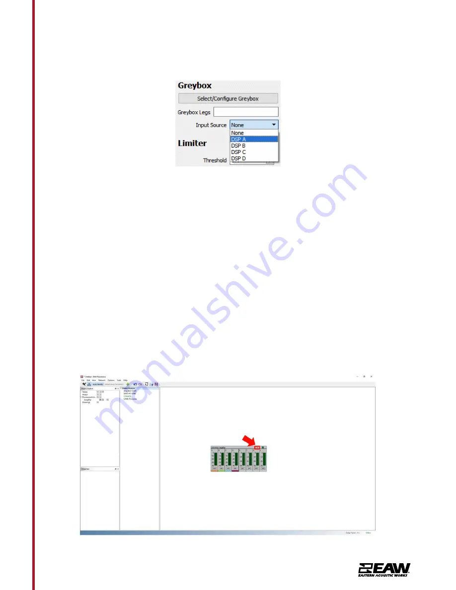
3. Greybox: 

Load EAW Greyboxes and set Input source (See pull down menu below).

4. Output Section: 

Adjust gain, invert polarity, and set delay or delay distance. Unity Gain and 

Invert Polarity is disabled once a Greybox is loaded.

5. Limiter: 

Set Voltage Threshold, as well as Attack and Release times.

6. Amp: 

Bridge amplifier output channels and select the load type in either voltage or ohms (an 

auto option is also available).

7. Input Channels: 

Signal meters and channel labels. To change a channel label, double click on 

the default letter/number and type in a friendly name.

8. Output Channels:

 Signal meters and channel labels. To change a channel label, double click 

on the default letter/number and type in a friendly name.

9. Input/Output Color Indicators: 

An easy method to distinguish which outputs are utilizing 

which input source (Assigned output channels will match the color of input channels).

Loading Greyboxes (EAW Speaker Preset Files) into UXA4410

To load a Greybox onto one of the UXA devices, click the 

Edit

 button to open the edit 

window.

Summary of Contents for QX Series

Page 1: ...Application Guide Passive Point Source...

Page 2: ...Matching 18 Going Online with UXA4410 18 UXA4410 Input Section 23 UXA4410 Output Section 24 Loading Greyboxes EAW Speaker Preset Files into UXA4410 25 Unify Processor Interfaces for UXA4410 Amplifier...

Page 3: ...nce in properly designing line array systems Software EAW Resolution 2 software is designed to assist in SPL predictions determine splay angles and calculate rigging limits for all line array items Al...

Page 4: ...MKC80 MKC120 Patented CSA coaxial horn provides superior control fidelity and output MKC80 MKC120 Integrated handle and pole mount MKC120 Integrated M10 mounting points Inherent weather resistance for...

Page 5: ...00 and MK5300 series Multiple mounting points for flexible mounting options MK5326i 120 x 60 MK5364i 60 x 45 MK5366i 60 x 60 MK5394i 90 x 45 MK5396i 90 x 60 MK5399i 90 x 90 User rotatable horns let co...

Page 6: ...ble Baltic birch construction Robust WP option custom colors High power compression drivers to handle lower octaves to manage crossover Spaced woofers for LF pattern control Large format rotatable hor...

Page 7: ...X566i 60 x 60 QX594i 90 x 45 QX596i 90 x 60 Spaced low frequency sources in two planes for broadband pattern control Large horn for extended pattern control Large format compression driver for precise...

Page 8: ...nstance if QX series is specified but cost is of concern MKD series is a viable solution with only a small sacrifice in performance Same could be said when looking at MKD series to MKi series Though t...

Page 9: ...992 5013 1 508 234 6158 www eaw com 9 Passive Point Source Application Guide Pairing with EAW Power Amplifiers Below are the recommended configurations when using UXA amps with point source products...

Page 10: ...Tel 800 992 5013 1 508 234 6158 www eaw com 10 Passive Point Source Application Guide UXA4410 Front Back Panel UXA4401 UXA4403...

Page 11: ...Source Application Guide Input Connections Neutrik NL4 2 pin barrier strip INPUT SIGNAL HPF 2 Way Single Amp LF HF AMP XVR HF LF HPF 2 Way Single Amp LF HF AMP XVR HF LF INPUT SIGNAL MKC50 MKC60 MK810...

Page 12: ...quency AMP User Supplied Power Amplifier or Integral Amplifier XVR Passive LPFs HPFs and EQ integral to the loudspeaker EAW Focusing Digital Signal Processor capable of implementing EAW WHITINSVILLE M...

Page 13: ...LF MF HF Low Frequency Mid Frequency High Frequency AMP User Supplied Power Amplifier or Integral Amplifier XVR Passive LPFs HPFs and EQ integral to the loudspeaker EAW Focusing Digital Signal Proces...

Page 14: ...ve LPFs HPFs and EQ integral to the loudspeaker EAW Focusing Digital Signal Processor capable of implementing EAW WHITINSVILLE MA USA S N PASSIVE INPUT LF HF CONNECT JUMPERS FOR PASSIVE OPERATION BI A...

Page 15: ...usive pressing one of the buttons will deselect any others that are active Pressing Utils will escape back to the Home screen 4 Page Selection Buttons When one of the buttons INPUT OUTPUT or UTILITY i...

Page 16: ...0 Amplifier Indicator This indicates when the amplifier protection systems are reducing the gain to keep the parameters of the amplifier within specification or when that the channel is clipping 11 Dr...

Page 17: ...th one 4 core cable i e Bi Amp On the UXA4810 model all outputs are Bi Amp each NL4 connector carries two amplifier outputs Channels 1 2 Channels 3 4 Channels 5 6 and Channels 7 8 In addition the chan...

Page 18: ...he connected load this will maximize the power that is available for the load Going Online with UXA4410 Before going online assure the computer being used is connected to the same Ethernet network as...

Page 19: ...Point Source Application Guide To add a processor or amplifier to the system click on the symbol next to Processors Amplifiers in the Project Explorer window Upon being prompted choose a name and a pr...

Page 20: ...4 6158 www eaw com 20 Passive Point Source Application Guide The selected device will now be loaded into the system In this case as offline To connect the processor or amplifier to the system start by...

Page 21: ...products will now appear listed under Online Devices Click and drag each detected device and drop it over the top of previously set up offline devices A prompt may appear if Resolution is not in sync...

Page 22: ...ices Click and drag each detected device and drop it over the top of previously set up offline devices A prompt may appear if Resolution is not in sync with the device Choose whether to push the Resol...

Page 23: ...nd hides the detail pane 2 EQ Filters Section Manually adjust settings for all Filters Use buttons to navigate from one band to the next There is an additional pull down menu to choose type of filter...

Page 24: ...ndicators An easy method to distinguish which outputs are utilizing which input source Assigned output channels will match the color of input channels UXA4410 Output Section 1 EQ Filter Graphic Window...

Page 25: ...or ohms an auto option is also available 7 Input Channels Signal meters and channel labels To change a channel label double click on the default letter number and type in a friendly name 8 Output Cha...

Page 26: ...800 992 5013 1 508 234 6158 www eaw com 26 Passive Point Source Application Guide Click any output channel then click on Select Configure Greybox On the main Greybox Configuration window click Add Gre...

Page 27: ...and exact Greybox configuration of the Loudspeaker Click OK to proceed The Greybox Configuration window should now be populated with set up options Here assign an input an output channel for each Leg...

Page 28: ...he Add an Amplifier window appears fill in each setting as specified by the Amplifier spec cut sheet Entry Method may either be by Voltage or Power Back to the Greybox configuration window the newly c...

Page 29: ...ted to turn off all amplifiers except one Refresh the network then Unify the processor to the Dante card Repeat this for each amplifier This will ensure that you are connecting the correct Amplifier P...

Page 30: ...ion needs to know the Dante address so routing can be done between devices in Resolution NOTE Processor or Amplifier control will work fine without a unified Dante port With the Unify Processors windo...

Page 31: ...cation Guide After the function is complete the linked interface may be viewed in the bottom pane as illustrated below Click Done to accept or Break to undo and reverse the action Under Online Devices...

Page 32: ...ne standard rack ear and one half rack extension piece as illustrated in Diagram 1a The installation and equipment rack should be configured to provide appropriate ventilation airflow space around the...

Page 33: ...underside of desks or wall mounted using connecting plate hardware The adhesive rubber feet should also be used in these circumstances to minimise the possibility of vibration between the amplifier an...

Page 34: ...d with rack ears attached and are primarily intended for standard 19 inch equipment rack installation If not to be installed in an equipment rack UXA4403 amplifiers can be placed free standing on a fl...

Page 35: ...Amplifier amplifier default LAN IP address is 192 168 64 100 Configure the laptop or desktop computer for a fixed IP address in the same IP range eg 192 168 64 10 with Subnet mask of 255 255 255 0 or...

Page 36: ...Diagram 4b illustrates the Input Tab Diagram 4a Configuration Dashboard display Diagram 4b Input Tab display Note When adjusting input gain the input level display should remain green If it displays...

Page 37: ...nu option enables inputs to be assigned to zones The GPIO Volume Control Diagram 4d option enables external volume control to be applied to individual zones The GPIO configuration menu can be found un...

Page 38: ...available for configuration will depend on the UXA Amplifier amplifier model and the input zone and output mode configuration The Routing menu Diagram 4f enables zones to be assigned to amplifier out...

Page 39: ...created Speaker preset library creation and management is described in Section 5 3 5 2 Select the appropriate zcp format speaker preset data file to import from either a Library or a computer folder T...

Page 40: ...a Low Pass and High Pass Filter as well as adjusting global gain Diagram 4l Diagram 4l Preset Crossover Gain The Speaker EQ in the preset menu allows for configuring customized parametric EQ on the o...

Page 41: ...70Hz If low frequency distortion is still audible increase the frequency setting one step at a time until the distortion is no longer audible Driver Alignment in the preset menu will allow for delay t...

Page 42: ...ier button can also be found under the Device menu The Backup Restore menu enables amplifier configuration data to be downloaded to an external archive and enables previously saved configuration files...

Page 43: ...im Gain Trim Input Sensitivity Input Gain Input Gain Input Selection Input Setup Zone Setup Routing Output Setup Output 1 Output 2 Output 3 Output 4 Zone Adjustment Parameters Speaker Preset Parameter...

Page 44: ...Tab is shown in Diagram 4c Select the zone to be configured The number of zones available and their channel format stereo or mono will depend on the amplifier model input setup and output mode Lo Z o...

Page 45: ...ntiometers via GPIO Note GPIO Pin 8 has a low output impedance and is able to supply a maximum current of 10mA Note GPIO Pin 1 and Pin 3 both offer ground connections Pin 1 is connected directly to th...

Page 46: ...o the amplifiers are made via RCA phono sockets connected in parallel with the balanced inputs Digital Inputs UXA amplifiers S PDIF stereo digital audio input connections are made via a single RCA Pho...

Page 47: ...afety precautions Rigging Design Practices Rigging a loudspeaker requires determining 1 The rigging methods and hardware that meet static shock dynamic and any other load requirements for supporting t...

Page 48: ...r brackets that are not included with the U Bracket kit Without the adapter brackets the U brackets cannot physically attach to the cabinets Each Adapter Bracket ships with mounting stud nut and washe...

Page 49: ...O circumstances is possible to suspend another loudspeaker under a QX when using available mounting points Doing so risks both damage to the speaker and imposes a serious safety risk The supported wei...

Page 50: ...d horizontally If one of these loudspeakers is to be deployed in a vertical orientation a different method must be used Use 1 4in or M6 Bolt for installation using slots as indicated below MKD1000 Ser...

Page 51: ...thods for MKD Series MKD800 MKD1000 MKD1200 Series have M10 mounting points on the top bottom and both sides of the cabinet so it may be flown in either a vertical or horizontal deployment There are a...

Page 52: ...com 52 Passive Point Source Application Guide Splay Brackets MKD1000 Series only 6mm Allen Wrench Required Tools Supplies Inventory your kit Part Part Name Quantity Reference Suspension Rigging Brack...

Page 53: ...ets are available in Resolution 2 to allow for exact configuration and angles that should be deployed Connect Cabinet Rigging Bracket to Bottom MKD1000 1 Position MKD1000 loudspeakers on side using pr...

Page 54: ...Tel 800 992 5013 1 508 234 6158 www eaw com 54 Passive Point Source Application Guide Select Angle Figure 2 above Figure 3 below Secure to bottom MKD Cabinet and select angles...

Page 55: ...ecure in place using supplied hardware screws Figure 4 Figure 4 Suspension Cabinet Bracket secured Note Using two people carefully alternate MKD1000 to other side and follow above steps to complete th...

Page 56: ...suspend or fly a pair of MKD1000 using only the cabinet bracket This configuration would be utilized if loudspeakers needed to be aimed directly down at a surface or coverage area Follow steps 1 3 as...

Page 57: ...13 1 508 234 6158 www eaw com 57 Passive Point Source Application Guide Figure 6 Secure bottom and top MKD1000 with Cabinet Bracket 8 To deploy connect shackles to rear rigging points on Cabinet Brack...

Page 58: ...ts for MK Series MK8100 MK2300i MK5300i Series products all have optional U Brackets that may be used These brackets my only be deployed horizontally If one of these loudspeakers is to be deployed in...

Page 59: ...Tel 800 992 5013 1 508 234 6158 www eaw com 59 Passive Point Source Application Guide...

Page 60: ...Tel 800 992 5013 1 508 234 6158 www eaw com 60 Passive Point Source Application Guide MK8100 U Bracket Instructions...

Page 61: ...be flown in either a vertical or horizontal deployment There are also two mounting points on the back to either be used for pull back or used in a ceiling speaker configuration NOTE Under NO circumsta...

Page 62: ...ilt Bracket for MKC50 60 1 Inventory your kit Item Description Quantity A EAW MKC Plastic Wall Mount Speaker Bracket 1 B EAW MKC Plastic Wall Mount Wall Bracket 1 C EAW MKC Plastic Wall Mount Link Bra...

Page 63: ...be used with direct exposure to elements and is not approved in situations where weather protection is required Pan and Tilt with Link Bracket installed on MKC60 Pan Tilt Bracket with Link Bracket 3 I...

Page 64: ...nt to permanent structure i All four mounting holes will need to mount to permanent structure utilizing approved mounting hardware ii Consider orientation of loudspeaker horizontal or vertical before...

Page 65: ...if tool access is improved with Link Bracket connected to the Wall Bracket or the Speaker Bracket ii Connect Link Bracket to Wall or Speaker Bracket using M6 screw with lock nut Tighten with a 4mm he...

Page 66: ...acket for damage Brackets with visible damage should be replaced and discarded e Inspect hardware securing the u bracket to the mounting surface for corrosion or looseness Tighten loose hardware and c...

Page 67: ...n Tilt Bracket for all MKC Models 1 Inventory your kit Item Description Quantity A EAW MKC Metal Wall Mount Speaker Bracket 1 B EAW MKC Metal Wall Mount Wall Bracket 1 C Button Head Hex Drive Screw 1...

Page 68: ...h d WARNING Take care when lifting larger MKC Series products to avoid harm or damage to product Cabinet Bracket showing mounting options Wall Bracket with Pivot Block removed 3 Installation of the MK...

Page 69: ...o mount to permanent structure i All four mounting holes will need to mount to permanent structure utilizing approved mounting hardware ii Consider orientation of loudspeaker horizontal or vertical be...

Page 70: ...raints of loudspeakers used with bracket NOTE Depending on orientation of the wall bracket A pan and tilt hardware configuration will vary i Loosen bolt and nut locking the current angle on the Pivot...

Page 71: ...As with any professional loudspeaker system routine maintenance must be conducted in order to ensure the longevity and safe consistent performance d Inspect the MKC Series Metal Pan Tilt Bracket for d...

Page 72: ...ation Guide U Brackets for MKC Series MKD526 Inventory your kit Item Description Quantity A Bracket 1 B Button Head Screw 2 C Flat Washer 2 D Split lock Washer 2 E Rubber Washer 2 F Socket Head Screw...

Page 73: ...d may result in damage injury or death e WARNING Take care when lifting MKC Series or MKD526 products to avoid harm or damage to product f WARNING MKC MKD526 brackets are for suspension of loudspeaker...

Page 74: ...n methods and materials the hardware for securing the bracket to the mounting surface is not supplied It is required that the use of hardware locking methods not limited to lock washers thread locker...

Page 75: ...NING Take care when handling and wear PPE gloves to protect from crushing and impacts with digits limbs and or product Note for weather protected applications using WP Series Loudspeakers apply user s...

Page 76: ...hree complete turns into the loudspeaker s two threaded mounting holes Leave as large a space as possible between the rubber washer E and the flat washer D WARNING HEAVY LIFTING MULTIPLE PERSON LIFT L...

Page 77: ...rdware Replace and discard corroded hardware g For weather protected applications using WP Series Loudspeakers inspect hardware sealants for cracking or gaps in sealant Replace damaged sealant with us...

Page 78: ...Tel 800 992 5013 1 508 234 6158 www eaw com 78 Passive Point Source Application Guide APPENDIX A MKD526 Bracketry Under Balcony Bracket WP not available Yoke Bracket U Bracket...

Page 79: ...Tel 800 992 5013 1 508 234 6158 www eaw com 79 Passive Point Source Application Guide APPENDIX B MKC Series Bracketry WP Brackets ONLY MKC50 MKC60 MKC80 MKC120...

Page 80: ...Tel 800 992 5013 1 508 234 6158 www eaw com 80 Passive Point Source Application Guide Inventory your kit Tools Needed 3mm 6mm Allen wrench MKC Series Small Ceiling Bracket...

Page 81: ...ons where weather protection is required Pan Tilt Bracket with Link Bracket 3 Installation of the MKC Series Pan Tilt Wall Bracket B to Ceiling Bracket F a Test fit MKC Series Ceiling Pan Tilt Bracket...

Page 82: ...ing bracket F i All four mounting holes will need to mount to ceiling bracket utilizing included mounting hardware ii Consider orientation of loudspeaker horizontal or vertical before securing wall br...

Page 83: ...o connect bracket to the speaker remove hardware from rear of MKC50 or MKC60 place speaker bracket over mounting pattern and secure with previously removed hardware Each mounting hole will correspond...

Page 84: ...th lock nut Tighten with a 4mm hex tool Do not tighten fully iii Connect Link Bracket to remaining Wall or Speaker Bracket using M6 screw with lock nut Tighten with a 4mm hex tool Do not tighten fully...

Page 85: ...acket for damage Brackets with visible damage should be replaced and discarded e Inspect hardware securing the u bracket to the mounting surface for corrosion or looseness Tighten loose hardware and c...

Page 86: ...Tel 800 992 5013 1 508 234 6158 www eaw com 86 Passive Point Source Application Guide Inventory your kit MKC Series Large Ceiling Bracket Tools Needed 2 13mm wrench 2 5mm 6mm Allen wrench...

Page 87: ...ng larger MKC Series products to avoid harm or damage to product Exploded view of ceiling bracket kit with plastic Pan Tilt Mount MKC80 utilizing Ceiling Bracket with Pan Tilt Bracket 3 Installation o...

Page 88: ...racket A i All four mounting holes will need to mount to ceiling bracket utilizing 4x M6x20 bolts D 4x Lock Washers C and 4x Flat Washers B ii Consider orientation of loudspeaker horizontal or vertica...

Page 89: ...es Loudspeaker configuration i Note if loudspeaker will need to pan or tilt or perform a combination of both options ii Consider orientation of loudspeaker horizontal or vertical before securing speak...

Page 90: ...mage should be replaced and discarded e Inspect hardware securing the bracket to the mounting surface for corrosion or looseness Tighten loose hardware and consider installing hardware locking methods...

Page 91: ...s were designed and engineered at our headquarters in Whitinsville MA USA and go through multiple quality checks during manufacturing We guarantee our loudspeakers against defects in workmanship mater...

Reviews: