


For more information visit: www.eaton.com
www.eaton.com
www.eaton.com
www.eaton.com
www.eaton.com
Instructions for
VSR-Series Type 5HK
Vacuum Motor Starter
IB01301027E
IB01301027E
Page 4
Page 4
Page 4
Page 4
Page 4
Effective: May 2008
Effective: May 2008
Effective: May 2008
Effective: May 2008
Effective: May 2008
Figures
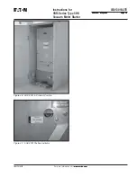
Figure 1-1 Outline and Dimensions in inches of Type 5HK-VSR Vacuum Motor Starter Replacement Unit ............. 6
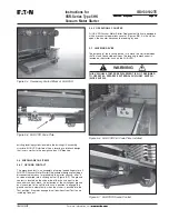
Figure 3-1 Typical 5HK-VSR Levering Crank .......................................................................................................... 8
Figure 3-2 Overhead Lifting of 5HK-VSR ............................................................................................................... 8
Figure 3-3 Front External View of 5HK-VSR Vacuum Starter Replacement Unit .................................................. 10
Figure 3-4 Rear External View of 5HK-VSR Vacuum Starter Replacement Unit ................................................... 11
Figure 4-1 Coil Control Board with Dip Switch .................................................................................................... 12
Figure 4-2 Coil Control Board Removal ............................................................................................................... 12
Figure 4-3 Alignment of 5HK-VSR ....................................................................................................................... 13
Figure 4-4 Insertion of HK-VSR (5HK-VSR-250 shown) ........................................................................................ 14
Figure 4-5 5HK-VSR in Disconnect Position ........................................................................................................ 14
Figure 4-6 5HK-VSR in Connect Position ............................................................................................................. 15
Figure 4-7 5HK-VSR Position Indicator ................................................................................................................ 15
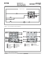
Figure 5-1 SL Front and Rear View Major Components ........................................................................................ 17
Figure 5-2 SL Rear View Major Components ....................................................................................................... 17
Figure 5-3 SL Contactors Assembly ..................................................................................................................... 18
Figure 5-4 Secondary Contact Block of 5HK-VSR ................................................................................................ 19
Figure 5-5 5HK-VSR Code Plate .......................................................................................................................... 19
Figure 5-6 5HK-VSR Cell Code Plate Installed .................................................................................................... 19
Figure 5-7 5HK-VSR Ground Contact ................................................................................................................... 19
Figure 6-1 Interrupter Wear Check ...................................................................................................................... 20
Figure 7-1 Loosening Locknut .............................................................................................................................. 22
Figure 7-2 Removing Clamp Securing Lower Terminal ......................................................................................... 22
Figure 7-3 Removing Bolt and Shunt Supports ..................................................................................................... 22
Figure 7-4 Removing Bolt Securing Upper Terminal ............................................................................................. 22
Figure 7-5 Removal of Vacuum Interrupter .......................................................................................................... 23
Figure 7-6 Installation of Bolt and Shunt Supports .............................................................................................. 23
Figure 7-7 Remove the Coil Mounting Angle ....................................................................................................... 24
Figure 7-8 Remove the Lockout Securing the Return Spring Bolt ........................................................................ 24
Figure 7-9 Unscrew the Return Spring Assembly ................................................................................................. 24
Figure 7-10 Install New Coils on Cores ................................................................................................................ 24
Figure 7-11 Stop Assembly Adjustment Block ...................................................................................................... 24
Figure 7-12 Remove the Two Mounting Screws Securing the Contact Assembly To Bearing Retainer ................... 25
Figure 7-13 Adjust the Gap Between Plunger and Operating Arm to .110 Inches .................................................. 25
Figure 7-14 Coil Core Retaining Bolt ................................................................................................................... 25
Figure 7-15 Alignment of Latch Components ....................................................................................................... 25
Figure 7-16 Location of Latch Assembly on Conductor Base Plate ...................................................................... 26
Figure 7-17 Set Gap Between Roller Bearing and Cam to .5mm (.020”) ............................................................... 26


