


For more information visit: www.eaton.com
www.eaton.com
www.eaton.com
www.eaton.com
www.eaton.com
Instructions for
VSR-Series Type 5HK
Vacuum Motor Starter
IB01301027E
Page 25
Page 25
Page 25
Page 25
Page 25
Effective: May 2008
Effective: May 2008
Effective: May 2008
Effective: May 2008
Effective: May 2008
IB01301027E
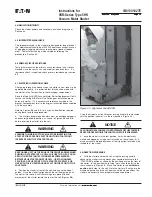
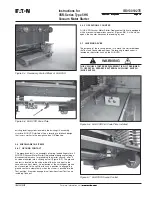
Figure 7-12 Remove the Two Mounting Screws Securing the
Contact Assembly To Bearing Retainer
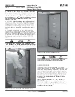
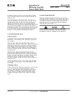
Figure 7-13 Adjust the Gap Between Plunger and Operating
Arm to .110 Inches
7.6 MECHANICAL LATCH
7.6.1 LATCH REMOVAL
1. Remove latch control wires from terminals 7 & 8 on contactor oil
control board.
2. Remove the four 8mm x 1.25 bolts from the underside of the
base plate that secure the latch assembly to the base plate.
3. Remove the two 6mm x 1.0 bolts from the front of the contactor
that secure the roller bracket assembly to the armature plate.
COIL CHECKOUT AND REPLACEMENT
If the contactor fails to open when the unlatch coil is energized, the
coil may be faulty. To determine if the coil has the proper resistance,
connect an ohmmeter across the coil leads where they are
connected to the bridge rectifier. Refer to Table 7.1 for the correct
impedance for the different voltage coils.
If the coil impedance is not within the range in Table 7.1, it must be
replaced. Follow the steps below for replacement.
1. Remove latch control wires from terminals 7 & 8 on contactor
coil control board.
2. Remove the four 8mm x 1.25 bolts from the underside of the
base plate that secure the latch assembly to the base plate.
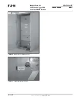
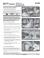
3. Remove latch coil retaining bolt (8mm x 1.25), Figure 7-14, and
remove all components secured by this bolt.
4. Remove the 4mm x .7 screw securing bridge diode to latch coil
bracket.
5. Remove old coil from core.
6. Insert coil core into new coil, insuring rubber gasket is between
core and coil bobbin.
s
t
l
o
V
l
i
o
C
e
c
n
a
d
e
p
m
I
4
2
5
9
.
0
-
7
7
.
0
8
4
5
5
.
3
-
5
9
.
2
5
2
1
/
0
2
1
/
0
1
1
9
1
.
1
1
-
7
9
.
0
1
0
4
2
/
0
2
2
7
5
.
4
5
-
7
5
.
4
4
Table 7.1 - Unlatch Coil Impedance
Figure 7-14 Coil Core Retaining Bolt
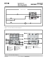
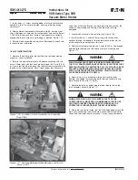
Figure 7-15 Alignment of Latch Components


