


For more information visit: www.eaton.com
www.eaton.com
www.eaton.com
www.eaton.com
www.eaton.com
Instructions for
VSR-Series Type 5HK
Vacuum Motor Starter
IB01301027E
IB01301027E
Page 26
Page 26
Page 26
Page 26
Page 26
Effective: May 2008
Effective: May 2008
Effective: May 2008
Effective: May 2008
Effective: May 2008
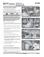
7. Install 4mm x .7 screw securing diode to latch coil bracket and
tighten to 9 lb-in. Do not over tighten, cracking of diode housing
could result.
8. Reassemble all components removed in step 3, insuring steel
shim is between coil core and coil core bracket, and secure 8mm x
1.25 bolt to latch base plate. Insure all components are correctly
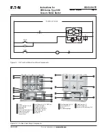
aligned and the coil wires are not binding or pinched, Figure 7-15.
9. Reinstall latch assembly and adjust as described in steps 3 to 8
in the section on Installation.
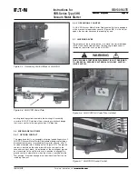
7.6.2 LATCH INSTALLATION
1. Remove the existing roller bracket from the contactor moving
armature, if one is attached.
2. Secure the new roller bracket and bearing assembly with two
6mm x 25mm bolts with lock washers and torque to 85 in-lb (9.6 N-
m). Insure that the side flanges of the roller bracket are parallel with
the end of the armature plate. Note: If bolts longer than 25mm are
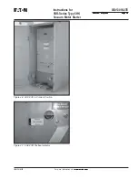
Figure 7-16 Location of Latch Assembly on Conductor
Base Plate
Figure 7-17 Set Gap Between Roller Bearing and Cam to
.5mm (.020”)
used, they will extend through the armature plate and prevent the
contactor from closing and sealing when the main coils are
energized.
3. Locate latch assembly into contactor, see Figure 7-16.
4. Install four 8mm x 1.25 bolts 16mm long, with lock and flat
washers through the bottom of the contactor base plate into the
latch base plate, do not tighten at this time.
5. With contactor energized, place a 0.5mm (0.020 in.) feeler gage
between roller bearing and rotating cam on lath assembly, see
Figure 7-17
FOLLOW NECESSARY PRECAUTIONS INCLUDING INSURING
THAT ALL TRANSFORMERS ARE PROPERLY ISOLATED BEFORE
APPLYING POWER TO CONTACTOR COIL. IF VOLTAGE IS BACK
FED INTO A TRANSFORMER, HIGH VOLTAGE WILL BE GENER-
ATED ON THE TRANSFORMER PRIMARY. HIGH VOLTAGE CAN
CAUSE SERIOUS INJURY OR DEATH.
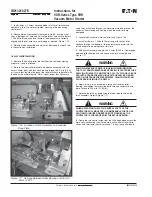
6. Apply force to latch assembly, sliding cam towards roller
bearing, and tighten four mounting bolts through contactor base-
plate. Torque to 200 in-lb (22.6 N-m).
7. Release the latch by depressing the latch release tab on the
latch assembly. Refer to Figure 7-17.
WHEN RELEASING THE LATCH SEVERAL PARTS OF THE
CONTACTOR WILL MOVE WITH CONSIDERABLE FORCE. USE
CAUTION TO INSURE FINGERS ARE NOT PINCHED AS THE
CONTACTOR IS FORCED OPEN BY THE RETURN SPRING.
8. Route the two control wires from the full bridge diode across the
main coils, connecting them to the main coil control wires with tie
straps, and terminate them at terminals 7 & 8 on the control board.
WARNING
WARNING


