Eaton VSR Series Instructions Manual Download Page 25

For more information visit: www.eaton.com

www.eaton.com

www.eaton.com

www.eaton.com

www.eaton.com

Instructions for
VSR-Series Type 5HK
Vacuum Motor Starter

IB01301027E

Page  23

Page  23

Page  23

Page  23

Page  23

Effective:  May 2008

Effective:  May 2008

Effective:  May 2008

Effective:  May 2008

Effective:  May 2008

IB01301027E

3. From the point the light flickers, rotate insulator on middle phase

bottle counter-clockwise three and twothirds turns to establish a
5.5mm open gap. Use markings on insulator to verify correct
rotation. (Two thirds turn is equal to 8 divisions that are molded
on the surface of the insulator.)

4. Slowly rotate the main shaft, closing the VI’s, until the middle

phase light is on. Adjust the insulators on the two outside
phases so that the lights on all three phases come on simulta-
neously, (DO NOT MOVE THE INSULATOR ON THE MIDDLE
PHASE) while rocking the main shaft open and closed.

5. Tighten locknuts securing threaded rod to top of each insulator.

Use bottle wrench to insure standoff insulator does not rotate
during this operation.

6. Perform test as described in section 6 on 

Vacuum Integrity

Check

 before returning contactor to service.

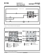
7.2  Coil Replacement

1. Remove the coil leads from terminals 5 and 6 on the control

board. Cut the wire-tie securing the coil leads to the baseplate.

2. Remove the coil mounting angle by removing the two angle

mounting bolts located on the bottom of the contactor baseplate.
(Figure 

7-7

). Be careful not to allow the angle to move abruptly

as the bolts are removed since there is pressure applied to the
angle by the return spring. Remove coil assembly from contactor.

3. Remove the locknut holding the return spring bolt on the back of

the mounting angle (Figure 

7-8

). Note: After removing locknut,

count the threads protruding through the mounting angle to
insure correct length during reassembly.

4. Unscrew the spring assembly by hand and remove from the

angle (Figure 

7-9

).

5. Slip the two coils from the cores.

6. Install the two new coils over the cores. (Figure 

7-10

)

7. Thread the return spring assembly into the mounting angle until

the locknut under the bottom spring retainer just contacts the
angle. The number of threads protruding through the mounting
angle should be the same as counted in step 3 above. Do not
overtighten since this would compress the return spring and
prevent the proper force from being applied to the operating
plate on opening. The rear locknut for the return bolt should then
be tightened on the back of the angle.

8. Secure the angle to the contactor baseplate using the two

mounting bolts. Sufficient force must be applied to the angle to
compress the return spring and allow the threaded holes in the
angle to align with the appropriate holes in the baseplate.

9. Connect the coil leads to the appropriate terminals on the control

board. Secure the leads using a wire tie and the hole in the
baseplate to insure that the leads do not become abraised.
Before the contactor is reinstalled, verify proper operation using
test power. When power is applied, the contactor should close
cleanly. When power is removed, the moving armature should
securely contact the stop assembly.

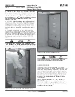
7.3  CONTROL BOARD CHECK AND REPLACEMENT

To verify the output of the control board, apply rated control voltage
to terminals one and two.

VERIFY THAT THE APPLIED POWER CANNOT BE FED BACK INTO
ANY CPT OR OTHER CIRCUIT, WHICH MAY GENERATE DANGER-
OUS VOLTAGES.

Using a standard hand-held multimeter, check the dc output of the
board at terminals 5 and 6. The voltage should be approximately 9
to 16 volts. If there is no output, the board must be replaced. If there
is an output voltage, but it is not within this range, remove the board
and verify the dip switch settings.

To remove the board, wires connected to terminals 1, 2, 5, and 6
must be disconnected. Make certain that the wires are properly
marked before disconnecting to insure the ability to reconnect them
to the proper terminal. After the wires are disconnected, loosen the
mounting screws located at the top and the bottom of the terminal
block. The board may now be withdrawn from its mounting
compartment.

Before a new board is installed, make certain that the dip switches
are properly set. Refer to Table 4.1 and Table 4.2. Installation is the
opposite of removal.

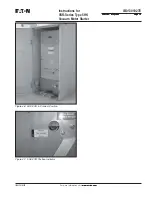
7.4  STOP ASSEMBLY REPLACEMENT

If the stop assembly becomes worn it should be replaced.

To replace, close the contactor with test power. Remove the two
bolts securing the assembly to the baseplate. Install a new
assembly. Hand-tighten bolts. Set gap between the armature plate
and stop to 0.534 in. 0.004 in. using adjustment block provided with
replacement stop assembly, torque bolts to 214 lb-in (24.2 N-M).
(See Figure 

7-11

)

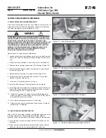
Figure 7-5  Removal of Vacuum Interrupter

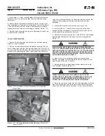
Figure 7-6  Installation of Bolt and Shunt Supports

WARNING

Summary of Contents for VSR Series

Page 1: ...it www eaton com www eaton com www eaton com www eaton com www eaton com IB01301027E IB01301027E Instructions for VSR Series Breaker To Vacuum Starter Replacement For Type 5HK Breakers 5HK VSR Vacuum...

Page 2: ......

Page 3: ...NSAS THEYMAYBEAPPLIEDTOTHISTYPEOFEQUIPMENTMUSTBE STRICTLYADHEREDTO THESEVACUUMMOTORSTARTERREPLACEMENTSAREDESIGNEDTO BEINSTALLEDPURSUANTTOTHENATIONALELECTRICALCODE NEC SERIOUSINJURY INCLUDINGDEATH CANR...

Page 4: ...13 4 5 INTERRUPTERWEARCHECK 13 4 6 PRIMARYCIRCUITRESISTANCE 13 4 7 ELECTRICALOPERATIONSCHECK 13 4 8 INSERTIONPROCEDURE 13 4 9 REMOVALPROCEDURE 15 SECTION5 DESCRIPTIONANDOPERATION 1 6 5 1 CONTACTOROPE...

Page 5: ...2008 Effective May 2008 Effective May 2008 IB01301027E Tables T able1 1 5HK VSRVacuumMotorStarterReplacementUnitAvailabilityandInterchangeability 5 T able1 2 5HK VSRVacuumMotorStarterReplacementUnitDi...

Page 6: ...nts 17 Figure 5 2 SL Rear View Major Components 17 Figure 5 3 SL Contactors Assembly 18 Figure 5 4 Secondary Contact Block of 5HK VSR 19 Figure 5 5 5HK VSR Code Plate 19 Figure 5 6 5HK VSR Cell Code P...

Page 7: ...ratings are inter changeable with each other 1 1 AVAILABLE5HK VSRMOTORSTARTERREPLACEMENTS Refer to Table 1 1 SATISFACTORYPERFORMANCEOFTHESEVACUUMMOTORSTARTER REPLACEMENTUNITSISCONTIGENTUPONPROPERAPPL...

Page 8: ...01027E Page 6 Page 6 Page 6 Page 6 Page 6 Effective May 2008 Effective May 2008 Effective May 2008 Effective May 2008 Effective May 2008 T able1 2 5HK VSRVacuumMotorStarterReplacementUnitDimensionsinI...

Page 9: ...y y y y y Alwaysremovethestarterfromtheenclosurebefore performinganymaintenance Failuretodosocouldresult inelectricalshockleadingtodeath severepersonnelinjury orpropertydamage y y y y y Proper persona...

Page 10: ...g Dolly Optional item used to help maneuver starter when out of structure Contact Wear Gauge Optional item used to check contact wear Style 5259C11H01 Lifting Sling Optional item used to lift the star...

Page 11: ...s should be arranged to permit free circulation of air on all sides and temporary heaters should be used to minimize condensation Moisture can cause rusting of metal parts and deterioration of high vo...

Page 12: ...ter IB01301027E IB01301027E Page 10 Page 10 Page 10 Page 10 Page 10 Effective May 2008 Effective May 2008 Effective May 2008 Effective May 2008 Effective May 2008 Figure 3 3 Front External View of 5HK...

Page 13: ...5HK Vacuum Motor Starter IB01301027E Page 11 Page 11 Page 11 Page 11 Page 11 Effective May 2008 Effective May 2008 Effective May 2008 Effective May 2008 Effective May 2008 IB01301027E Figure 3 4 Rear...

Page 14: ...he starter for any damage that occurred during shipment storage and installation Set the dip switches in the coil control board for the proper control voltage and dropout time Figures 4 1 and 4 2 and...

Page 15: ...bolted in position as shown in Figures 3 3 and 3 4 before inserting the starter into the cell EXAMINE THE INSIDE OF THE CELL BEFORE INSERTING THE STARTER FOR EXCESSIVE DIRT OR ANYTHINGTHAT MIGHT INTER...

Page 16: ...ce by the levering arms resting completely against the positive stops located on the starter truck This is the fully connected position Figure 4 6 The position indicator on the starter will show TEST...

Page 17: ...m Instructions for VSR Series Type 5HK Vacuum Motor Starter IB01301027E Page 15 Page 15 Page 15 Page 15 Page 15 Effective May 2008 Effective May 2008 Effective May 2008 Effective May 2008 Effective Ma...

Page 18: ...M coils establish a magnetic field within the interrupter during fault conditions The field disperses the arc during fault current interruption allowing the contactor to interrupt a very high fault c...

Page 19: ...3 Moving Armature Plate Optional Aux Contacts Stop Assembly Baseplate 8 9 10 11 12 13 14 Frame Front Mounting Holes 4 Operating Plate Main Shaft Aux Contact Operating Lever Standard Aux Contacts Coil...

Page 20: ...nt are recessed to prevent accidental short circuiting of the control circuits These secondary disconnects mate in both the operating and test positions No special jumper is required Mechanical stops...

Page 21: ...H MOC SWITCH Figure 5 4 Secondary Contact Block of 5HK VSR Figure 5 5 5HK VSR Code Plate WARNING Figure 5 7 5HK VSR Ground Contact existing levering system located in the existing HK assembly structur...

Page 22: ...NCE BETWEENTHE OPEN CONTACTS THE LEVELS OF RADIATION GENERATED AT THE RECOMMENDED TEST VOLTAGES AND NORMAL CONTACTOR OPEN GAP SPACING ARE EXTREMELY LOW HOWEVER AS A PRECAUTIONARY MEASURE IT IS RECOMME...

Page 23: ...achine with output potential at zero and increase to the test voltage Maintain the test voltage for one minute Repeat for the remaining phases Successful withstand indicates satisfactory insulation st...

Page 24: ...to housing Figure 7 2 4 Remove bolt and shunt supports securing end of lower terminal to housing Figure 7 3 5 Remove the bolt securing VI to upper terminal Figure 7 4 6 Hold insulator down and rotate...

Page 25: ...ould compress the return spring and prevent the proper force from being applied to the operating plate on opening The rear locknut for the return bolt should then be tightened on the back of the angle...

Page 26: ...mps through the contacts for a short period of time If one or more of the auxiliary contacts fail it is recommended that the complete contact block assembly be replaced Disconnect wiring to each conta...

Page 27: ...latch coil is energized the coil may be faulty To determine if the coil has the proper resistance connect an ohmmeter across the coil leads where they are connected to the bridge rectifier Refer to Ta...

Page 28: ...etween Roller Bearing and Cam to 5mm 020 used they will extend through the armature plate and prevent the contactor from closing and sealing when the main coils are energized 3 Locate latch assembly i...

Page 29: ...u u c a V 3 0 G 8 5 A 7 4 1 2 d r a o B l o r t n o C l i o C 4 0 G 8 5 A 7 4 1 2 C N 2 O N 2 t i K t c a t n o C y r a i l i x u A 5 0 G 8 5 A 7 4 1 2 r o t c a t n o C d e h c t a L r o f C N 3 O N...

Page 30: ......

Page 31: ......

Page 32: ...ILITY OR WARRANTIES ARISING FROM COURSE OF DEALING OR USAGE OF TRADE ARE MADE REGARDING THE INFORMATION RECOMMENDATIONS AND DESCRIPTIONS CON TAINED HEREIN In no event will Eaton Corporation be respons...

Reviews: